Models Step
The Models step contains the following elements.
Model list
Lists all names and types of the models in the project.
 Add Model
|
Connect to FMU Model |
Adds a new entry to the model list and allows you to connect to an FMU model (version 2.x). |
|
Connect to Simulink Model |
Adds a new entry to the model list and allows you to connect to a Simulink® model. |
|
Connect to TSim Plugin |
Adds a new entry to the model list and allows to connect to a TSiM Plugin model. |
|
Connect to ASCET6-PSL Model |
Adds a new entry to the model list and allows to connect to an ASCET PSL (PC Simulation Target) model. |
|
Import ASCMO Model |
Opens an open file dialog where you can select an ASCMO-STATIC or ASCMO-DYNAMIC model (*.ascmo or *.ascmodyn) to add a new entry to the model list. |
Rename
Opens a window, where you can rename the selected model.
Delete Models
Deletes selected models selected in the table from the project. You can use the standard Ctrl/Shift selection functions in the table
Input Mapping
The Input Mapping area provides editing options for the model selected in the Model list. These options are different for each model:
FMU Model Variant
-
FMU Model field with
 and Validate All button
You can enter or select path and name of a *.fmu model file. %ProjectPath% will be replaced with MOCA project path.
- FMU Parallelization checkbox: activates/deactivates parallelization of FMUs to speed up optimization.
-
Reset Mode combo box
Select the desired reset mode, depending on the selection this has an influence on FMU optimization performance. See tooltip for more details.
-
Steady State checkbox
Activate the checkbox, if you are using a steady state model.
Use
 to open and configure Steady State Options. Enter time in seconds for Simulation Step Size (base sample time of the model), Time until steady state and Average last (average interval duration at the end of the steady state). See also Steady State .
 -
"Parameter Mapping" area
-
mapping table
Column Name
Meaning
MOCA Parameter
Shows the MOCA parameters that have been mapped to FMU elements.
Info
For a valid mapping, this column shows the parameter type (e.g., Scalar or Map[3, 4]).
For an invalid mapping, this column shows unknown or, in red font, the reason why the mapping is invalid. Possible reasons are type mismatch or multiple mapping of an FMU element.
You can use the Validate All button to resolve the invalidity.
Table Data FMU
Shows the content of the Table Data/field of the parameter.
Breakpoints 1 –
Breakpoints 4
Shows the name of the FMU parameter.
Transpose Table Data
For
MatrixandMap(Parameter Type) the table data can be transposed.Column Major
Usually the data is interpreted in row-major order. If data should be interpreted in column-major order, select the checkbox.
-
Scan
Opens Scan <Model Name> for Parameter Mapping where you can create mappings by searching the FMU.
-
Add
Opens Add FMU to MOCA Parameter Mapping where you can select a new mapping.
-
Edit
Opens "Edit FMU to MOCA Parameter Mapping" window where you can edit the selected mapping.
-
Delete
Deletes selected mapping.
-
Get Calibration from FMU
Gets axes and calibration from FMU Model description.xml.
-
Export Mappings
Exports all mappings into a *.csv file.
-
Import Mappings
Imports all mappings from a *.csv file.
-
-
"Input Mapping" area
-
mapping table
Column Name
Meaning
FMU Name
Shows the names of FMU elements that have been mapped to MOCA inputs.
MOCA Name
Shows the MOCA inputs that have been mapped to FMU elements.
Info
For a valid mapping, this column shows the input type (e.g., Scalar or Map[3, 4]).
For an invalid mapping, this column shows unknown or, in red font, the reason why the mapping is invalid. Possible reasons are type mismatch or multiple mapping of an FMU element.
You can use the Validate All button to resolve the invalidity.
-
Add
Opens Add Input Mapping where you can select a new mapping.
-
Edit
Opens "Edit FMU to MOCA Input Mapping" window where you can edit the selected mapping.
-
 /
/ 
Moves selected Input mapping up/down the list.
Note
Using
/ in the Model Step after building the function has an impact on the order of arguments in the Function. -
Delete
Deletes selected Input mapping(s).
-
-
"Output Mapping" area
-
mapping table
Column Name
Meaning
FMU Name
Shows the names of FMU elements that have been mapped to MOCA outputs.
Info
For a valid mapping, this column shows the output type (e.g., Scalar or Map[3, 4]).
For an invalid mapping, this column shows unknown or, in red font, the reason why the mapping is invalid. Possible reasons are type mismatch or multiple mapping of an FMU element.
You can use the Validate All button to resolve the invalidity.
-
Add
Opens "Select FMU Outputs" window where you can select a new mapping.
-
/
Moves selected Output mapping up/down the list.
Note
Using
/ in the Model Step after building the function has an impact on the order of arguments in the Function. -
Delete
Deletes selected Output mapping(s).
-
Simulink Model Variant
-
Pre Load Script field with
buttonYou can enter or select a path and name of an executable M-script that will be run before the model is loaded. %ProjectPath% will be replaced with MOCA project path.
-
Simulink Model field with
and Open Model buttonYou can enter or select a path and name of the Simulink® model (*.mdl: before R2012a or *.slx: from R2012a) to be optimized. A click on Open Model opens the model in Simulink®.
-
Post Load Script field with
buttonYou can enter or select a path and name of an executable M-script that will be run after the model has been loaded.
-
Data sample time field
The sample time of the measured data.
-
Data Sample Time: Enter a value which is given as input to Simulink®. This field is only editable with static data (without time channel). Usually this value is the same as the fixed step width of the model.
or
Time per Step (related to Steady State): Enter the value for simulation duration per row of data.
-
Steady State checkbox and Average last [s] field
Activate this option, if you are using a steady state model.
If steady State is activated, enter time in seconds to average the last values and determine a mean value.
-
Allow Fast Restart checkbox
Deactivate this option to disable “Fast Restart” of Simulink® models e.g. for S-Functions which don't initialize correctly with “Fast Restart”.
-
See also Mapping Simulink® Parameters and Scanning the Simulink® Model and Mapping Parameters.
In the Enumerations tab the mapped parameters of a subsystem mask of the Simulink® model and values are listed.
-
See also Mapping Simulink® Inputs.
-
See also Mapping Simulink® Outputs.
-
Validate
Validates the Simulink® model. Possible errors are reported. If the test is successful, a success message is displayed.
-
Set Calibration checkbox
Activate to transfer the current calibration in ASCMO-MOCA to Simulink for verification. If deactivated, the original Simulink® calibration is used for verification.

 .
. .
. .
.  .
. .
.TSiM Plugin
-
"TSiM Plugin" field with the
and Validate button.You can enter or select a path and name of the TSiM Plugin.
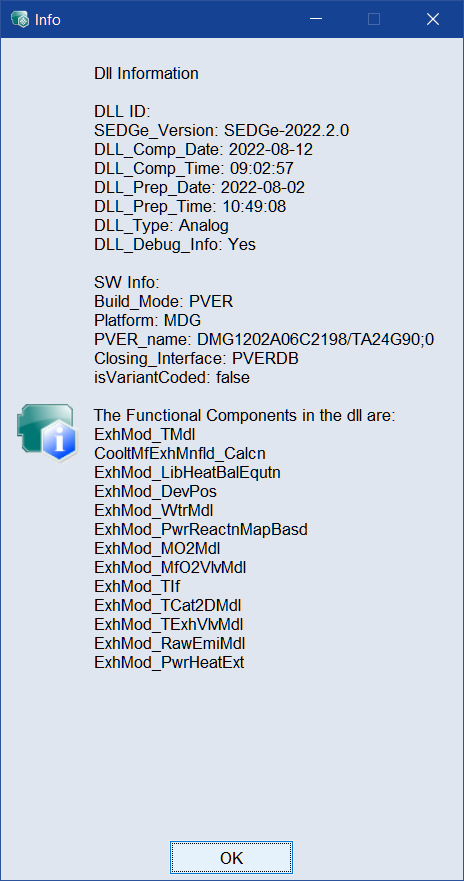
Click
to select a TSiM Plugin (*.mexw64) from an open file dialog.Click
Validate to check whether the model can be loaded and whether the configurations are valid. The model is not executed. It can automatically repair problems with group axes.Click
 to open the
  "Info" window. The window displays information about the functions and the version of the TSiM Plugin. Depending on the version of the TSiM Plugin, different information is displayed.
 -
Steady State checkbox
Activate the checkbox, if you are using a steady state model.
Use
to open and configure Steady State Options. Enter time in seconds for Simulation Step Size (base sample time of the model), Time until steady state and Average last (average interval duration at the end of the steady state). See also Steady State ."Simulation Step Size" drop-down list to set the model step width. Current sample rate and calculated recommended sample rate is shown in the tooltip. "Multi Rate" must be chosen during data import in "Time Base" settings. Only usable for "Import Dynamic Data" within Data Step. See ASCMO Data Import .
- DLL Parallelization checkbox: activates/deactivates Parallelization of DLLs to speed up optimization.
-
DLL Initialization: opens the DLL Initialization window, where you can set the initial value.
-
"Input Mapping" area
-
mapping table
Column Name
Meaning
TSim Name
Shows the names of TSim elements that have been mapped to MOCA inputs.
MOCA Name
Shows the MOCA inputs that have been mapped to TSim elements.
Info
For an invalid mapping, this column shows, in red font, the reason why the mapping is invalid after using Validate All button. Possible reasons are type mismatch or missing element.
-
Add
Opens Add Input Mapping where you can select a new mapping.
-
Edit
Opens "Edit TSim to MOCA Input Mapping" window where you can edit the selected mapping.
-
/
Moves selected Input mapping up/down the list.
Note
Using
/ in the Model Step after building the function has an impact on the order of arguments in the Function. -
Delete
Deletes selected Input mapping(s).
-
-
"Parameter Mapping" area
-
mapping table
Column Name
Meaning
TSim Name
Shows the names of TSiM Plugin elements that have been mapped to MOCA parameters.
MOCA Name
Shows the MOCA parameters that have been mapped to TSiM PlugIn elements.
Info
For an invalid mapping, this column shows, in red font, the reason why the mapping is invalid after using Validate All button. Possible reasons are type mismatch or missing element.
-
Add
Opens Add Parameter Mapping where you can select a new mapping.
-
Edit
Opens "Edit TSim to MOCA Parameter Mapping" window where you can edit the selected mapping.
-
Delete
Deletes selected mapping.
-
-
"Output Mapping" area
-
mapping table
Column Name
Meaning
TSim Name
Shows the names of TSiM Plugin elements that have been mapped to MOCA outputs.
Info
For an invalid mapping, this column shows, in red font, the reason why the mapping is invalid after using Validate All button. Possible reasons are type mismatch or missing element.
-
Add
Opens Select <Model> Outputs where you can select a new output mapping.
-
/
Moves selected output mapping up/down the list.
Note
Using
/ in the Model Step after building the function has an impact on the order of arguments in the Function. -
Delete
Deletes selected Output mapping(s).
-
ASCET6-PSL Model Variant
-
"ASCET-PSL Model" field with
and Validate All buttonYou can enter or select path and name of an ASCET-PSL DLL file. %ProjectPath% will be replaced with MOCA project path.
-
"Input Mapping" area
-
mapping table
Column Name
Meaning
ASCET Name
Shows the names of ASCET elements that have been mapped to MOCA inputs.
MOCA Name
Shows the MOCA inputs that have been mapped to ASCET elements.
Info
For a valid mapping, this column shows the input type (e.g., Scalar or Map[3, 4]).
For an invalid mapping, this column shows, in red font, the reason why the mapping is invalid. Possible reasons are type mismatch or multiple mapping of an ASCET element.
-
Add
Opens "Add Input Mapping" window where you can select a new mapping.
-
Edit
Opens "Edit ASCET to MOCA Input Mapping" window where you can edit the selected mapping.
-
/
Moves selected Input mapping up/down the list.
Note
Using
/ in the Model Step after building the function has an impact on the order of arguments in the Function. -
Delete
Deletes selected Input mapping(s).
-
-
"Parameter Mapping" area
-
mapping table
Column Name
Meaning
ASCET Name
Shows the names of ASCET elements that have been mapped to MOCA parameters.
MOCA Name
Shows the MOCA parameters that have been mapped to ASCET elements.
Info
For a valid mapping, this column shows the parameter type (e.g., Scalar or Map[3, 4]).
For an invalid mapping, this column shows, in red font, the reason why the mapping is invalid. Possible reasons are type mismatch or multiple mapping of an ASCET element.
-
Add
Opens Add Parameter Mapping where you can select a new mapping.
-
Edit
Opens "Edit ASCET to MOCA Parameter Mapping" window where you can edit the selected mapping.
-
Delete
Deletes selected mapping.
-
-
"Output Mapping" area
-
mapping table
Column Name
Meaning
ASCET Name
Shows the names of ASCET elements that have been mapped to MOCA outputs.
Info
For a valid mapping, this column shows the output type (e.g., Scalar or Map[3, 4]).
For an invalid mapping, this column shows, in red font, the reason why the mapping is invalid. Possible reasons are type mismatch or multiple mapping of an ASCET element.
-
Add
Opens Select <Model> Outputs where you can select a new Output mapping.
-
/
Moves selected Output mapping up/down the list.
Note
Using
/ in the Model Step after building the function has an impact on the order of arguments in the Function. -
Delete
Deletes selected Output mapping(s).
-
ASCMO Model Variant
-
Import Models: Select the ASCMO outputs to import.
-
Input Mapping
Column Name
Meaning
ASCMO Input Name
Shows the names of the ASCMO-STATIC or ASCMO-DYNAMIC inputs.
MOCA Name
Allows you to map an ASCMO-STATIC or ASCMO-DYNAMIC input to a MOCA input channel or function node.
ASCMO inputs and MOCA input channels or function nodes with matching names are mapped automatically.
-
Initial Output Value
If a model contains output initialization, the first measured or estimated output value is used to initialize its internal state.
Column Name
Meaning
Signal or Value
Shows the names of the ASCMO-DYNAMIC output.
MOCA Name
Allows you to map an ASCMO-DYNAMIC output to a function node or a data channel. The first value of a data channel is used as model initialization. In a model formula in the Function Step the last value of the model inputs correspond to the initialization.
Click in the column and type a value to manually set the initial value.
ASCMO outputs and MOCA function nodes with matching names are mapped automatically.
See also