Mapping Simulink® Inputs
In the Simulink Inputs Mapping area, imported data columns or nodes from the ASCMO-MOCA project can be mapped to the Simulink model inputs.
To automatically scan the Simulink model for inputs, proceed as follows:
-
In the Simulink Inputs Mapping area, click Scan Model.
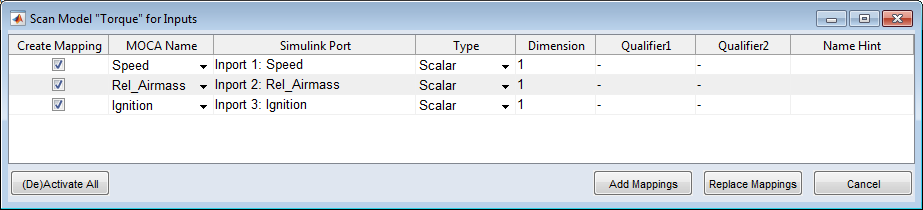
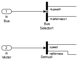
The model is scanned for Inport and From Workspace blocks. The results are then presented in the Scan Model <model_name> for Inputs window
-
 If necessary, enter the dimension and qualifiers manually.
 -
In the Create Mapping column, activate the checkboxes in all rows you want to map.
-
Click Add Mappings to add the selected mappings to the Simulink Inputs Mapping list.
With Add Mappings, existing content in the Simulink Inputs Mapping list is kept. If an existing row is selected again, this selection is ignored and a message is issued in the log window.
Replace Mappings removes existing content in the Simulink Inputs Mapping list.
After clicking Add/Replace Mappings, the Simulink Inputs Mapping table is filled.
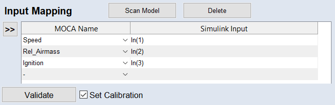
The notation Speed | In(1) means that the first Simulink Input data column is passed as Speed.
A list of possible notations is given in
See also
"Scan Model <model_name> for Inputs/Outputs" Window