Parameters for ES635 Lambda Module
The following lists shows the module parameters for the ES635 Lambda module. The module parameters can be stored both in a configuration file on the PC and in the device memory itself; they are both displayed in the Daisy Chain configuration program. The values on the tabs are updated every 500 ms.
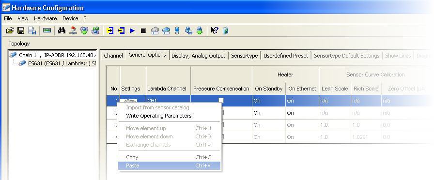
If you want to download configuration parameters to the device, you can either download the complete configuration or download and apply selected parameter settings.
Moreover, you can copy settings from a device and paste it to the configuration on the PC, or you can copy and paste settings within a configuration on the PC:
Note |
Please note that in standard device mode, only those parameters
are displayed that are used in daily tasks. In the advanced device mode,
additional parameters
which are only required for extended administrative tasks are also displayed. |
Parameters in standard device mode
Shows a consecutive number for each entry in the hardware configuration table.
You cannot edit this field.
Shows consecutive numbers for the Lambda channels.
Note |
For Lambda modules with only one channel, this column always displays CH1. |
Shows the name of the signal, i.e. the name of the measurement variable that is assigned to the corresponding channel.
The signal name can be edited.
Shows the physical unit for displaying the measure variable.
The unit appears in the corresponding measure windows.
The unit cannot be edited.
Defines the default acquisition rate necessary for your
measurement task.
The acquisition rate can be selected only for the Ip
(pumping current) channel; the rates of the first 5 channels will be set
accordingly.
The acquisition rate for Ri (internal resistance) and T (sensor temperature)
are always set to the same value.
The acquisition rate for the Pamb (ambient pressure) channel is always
set to the value 1s.
The rate given in the table is used as default rate within the measuring environment (e.g. INCA Experiment Environment), but you can overwrite it (e.g. in INCA's Configure Variables dialog).
Note |
A large number of channels with high acquisition rate can push your system to its performance limits. |
Defines the current 3dB cutoff frequency of the IIR low pass filter for the signal conditioning of the channel. Which settings are possible depends on the current acquisition rate.
You can either manually select the desired cutoff frequency from the list or switch off the IIR filter.
Enter the lower limit of the expected physical measurement range.
This value is stored with the hardware configuration and used as the default display range for measurement windows in the measuring environment (e.g. INCA Experiment Environment).
Enter the upper limit of the expected physical measurement range.
This value is stored with the hardware configuration and used as the default display range for measurement windows in the measuring environment (e.g. INCA Experiment Environment).
Enter any comment for that signal.
Shows a consecutive number for each entry in the hardware configuration table.
You cannot edit this field.
The device settings can be stored both in a configuration file on the PC and in the device memory itself.
| The values displayed in this table row show the parameters settings that are stored in the configuration file on the PC. | ||
| The values in this table row show the parameter settings that are stored in the device itself.
|

Shows consecutive numbers for the Lambda channels.
Note |
For Lambda modules with only one channel, this column always displays CH1. |
Air pressure and pressure in the exhaust gas have a major impact on the measuring accuracy of the Lambda sensor for the pump current. For that reason, different formulas can be used for correction of the pump current in the lean and the rich range.
When pressure compensation is activated, the value for the pump current will be adjusted according to air pressure or exhaust pressure, depending on the selected setting:
None
Automatic pressure compensation is switched off.
Ambient
Ambient pressure compensation is activated. The ambient air pressure is measured, and the influence on the signal of the Lambda sensor is compensated.
This setting is recommended if large altitude changes are expected.
External
Exhaust pressure compensation is activated. The pressure in the exhaust system is measured by an external pressure sensor, and the influence on the signal of the Lambda sensor is compensated. The measured exhaust pressure is available as measurement signal in the measurement and application software.
This setting is recommended for engines with high exhaust pressure (e.g. turbo engines or with particle filters).
If the Lambda module is in standby mode (i.e. it is not connected via Ethernet to the PC), you can select the operating mode for the Lambda sensor heating:
On
The heater is always switched on.
Off (default setting)
The heater is always switched off.
External Signal
The heater is controlled by means of an external signal.
Shows the correction factor for the Lambda module in the lean range. A value of 1.0 means that there is no deviation.
Note |
You can determine the correction factor by for the Lambda module, see Calibrating a Lambda Module by correcting the Sensor Curve. |
Shows the correction factor for the Lambda module in the rich range. A value of 1.0 means that there is no deviation.
Note |
You can determine the correction factor for the Lambda module, see Calibrating a Lambda Module by correcting the Sensor Curve. |
Shows the corrective current offset for the Lambda module in the zero current range. A value of 0.0 means that there is no deviation.
Note |
You can determine the corrective current for the Lambda module, see Calibrating a Lambda Module by correcting the Sensor Curve. |
Determines the behavior for automatic sensor detection:
Note |
Automatic sensor detection requires the ETAS Lambda sensor splitter cable. If a device is connected, the setting for this parameter is read from and controlled by the device. In standard device mode, the setting for this parameter can not be changed. |
Off
Automatic sensor detection is switched off. You can select any set of pre-defined configuration parameters from the Presets field on the Sensor Preset tab.
Sensor Defaults
The Lambda module detects automatically the sensor type via a memory chip in the sensor splitter cable. You can select any set of pre-defined configuration parameters from the Presets field on the Sensor Preset tab that matches the group of sensors that the detected sensor type belongs to.
Example: The detected sensor belongs to the group LSU4.2/LSU4.7. In this case, you can select from the following presets:
- 4.2-80
- 4.2/4.7
- any user defined configuration assigned to the detected group LSU4.2/LSU4.7.User Defined Defaults
The default settings are automatically assigned according to the group of sensors that the detected sensor type belongs to; the assignment can not be changed. Since there can be more than one set of pre-defined configuration parameters for each group of sensor types, the default preset for each group that will be automatically assigned is defined on the Sensortype Default Settings tab.
On this tab, you can define settings for the display on the hardware device itself. The tab contains three rows: one defines the analog output which can be used for displaying data on an external device, and two define the two LC displays on the device itself.
Shows a consecutive number for each entry in the hardware configuration table.
You cannot edit this field.
The device settings can be stored both in a configuration file on the PC and in the device memory itself.
| The values displayed in this table row show the parameters settings that are stored in the configuration file on the PC. | ||
| The values in this table row show the parameter settings that are stored in the device itself.
|
The three rows on this tab list the three output types offered by the Lambda module: an analog output which can be used for displaying data on an external device, and the two LC displays on the device itself. For the two LC displays, you can select whether they shall be activated or disabled.
On
The display is activated on the device.
Off
This display will not be used; you can not define any settings for that display.
Select the Lambda channel that is to be used at the corresponding output. It is also possible to display two signals from the same channel on the two different LC displays.
Note |
For Lambda modules with only one channel, this column always displays CH1. |
Select the measurement signal that is to be used at the corresponding output.
The signal can be filtered for a convenient usage of the measurement values.
Settings for analog output:
For the analog output, you can choose between different filter frequencies or disabling the filter. Whenever fast responses on Lambda transients are required, select Off to switch off filtering.
Settings for LC displays:
You can select between slow and fast. Slow is useful for more convenient reading of the values on the display.
The output voltage at the analog output of
the Lambda module is parametrizable by setting an offset (deviation) and
gain (multiplier). These will be used as follows to calculate the output
voltage from the sensor current:
Uout = offset + gain * I
With this parameter, you can set the offset for the output voltage.
Note |
Each measurement signal can be set to a different offset value. |
The output voltage at the analog output of
the Lambda module is parametrizable by setting an offset (deviation) and
gain (multiplier). These will be used as follows to calculate the output
voltage from the sensor current:
Uout = offset + gain * I
With this parameter, you can set the gain for the output voltage.
Note |
Each measurement signal can be set to a different gain value. |
Defines the resolution of the LC display on the device. You can select between fine and coarse resolution.
Defines whether standard or advanced device mode shall be activated for the LC display on the device.
standard
Provides functions on the display that are relevant for standard use cases.
advanced
Provides standard functions on the display, plus additional functions that might be relevant for special use cases. For further information please see the corresponding hardware manual.
Shows a consecutive number for each entry in the hardware configuration table.
You cannot edit this field.
The device settings can be stored both in a configuration file on the PC and in the device memory itself.
| The values displayed in this table row show the parameters settings that are stored in the configuration file on the PC. | ||
| The values in this table row show the parameter settings that are stored in the device itself.
|
Shows consecutive numbers for the Lambda channels.
Note |
For Lambda modules with only one channel, this column always displays CH1. |
The entry in this field determines which set of pre-configured settings is applied for the sensor-type used in the Lambda device.
According to the settings in the Daisy Chain configuration program, you can either select from a number of entries, or the sensor configuration is automatically assigned:
- If the parameter Sensor Detection on the General
tab is set to User Defined Defaults:
The presets for the detected group of sensor types are automatically assigned; you can not select another set of pre-defined settings. - If the parameter Sensor Detection on the General
tab is set to Sensor Defaults:
You can select from all sets of pre-defined settings that match the detected group of sensor types. - If the parameter Sensor Detection on the General
tab is set to Off:
You can select any preset from all available sets of pre-defined settings.
Note |
If the device is physically connected, the settings for the parameter Sensor Detection is read from the connected device itself. |
Shows the type of Lambda sensor family that was detected by TEDS.
Shows the type of the Lambda sensor that is connected to the device.
Note |
If None is displayed in the Presets field (i.e. if there is no set of pre-defined settings assigned) and the group of sensor types could not be automatically detected, you must select the appropriate sensor manually. |
Displays the nominal value of the Lambda sensor's inner resistance, which is used for heater control.
Note |
If Not Defined is selected in the Detected Group and Sensor fields, you must manually set the appropriate value. |
Shows the name of the characteristic line used by the Lambda module for defining the ramp-up of the heater voltage after start-up until the heater controller takes control.
Note |
You can use any pre-defined or user-defined line. Additional lines can be added via the File menu, see Importing Characteristic Lines from a File. |
Shows the name of the characteristic line used by the Lambda module for calculating the signals Lambda, A/F, 1/Lambda, and F/A from the input signal Ip.
Note |
You can use any pre-defined or user-defined line, or you
can select the entry Analytic to rematch the curve
used in the calculation process (for sensors of the types ZFAS-U2
and ZFAS-U2-D, the entry Analytic
is not available). If the Sensor Detection parameter on the General Options tab is set to User Defined Defaults, the Lambda Line field is read-only. |
Shows the name of the characteristic line used by the Lambda module for describing the relation between the sensor temperature and the internal resistance.
Note |
You can use any pre-defined or user-defined line. Additional lines can be added via the File menu, see Importing Characteristic Lines from a File. |
If Analytic is selected for the Lambda line instead of a pre-defined line, you can use this tab to enter the current climatic conditions and the use of fuel mixtures that will be taken into account to rematch the curve used in the calculation process.
Moreover, you can enter hydrogen shifts, which occur due to hydrogen residue in the exhaust gas and can also lead to measuring deviations. To correct hydrogen shift, you can adapt the curve by changing the interval defined by the upper and lower thresholds. The mean deviation (Lambda at IP=0) acts as the parameter for interpolating the actual Lambda value.
Shows a consecutive number for each entry in the hardware configuration table.
You cannot edit this field.
The device settings can be stored both in a configuration file on the PC and in the device memory itself.
| The values displayed in this table row show the parameters settings that are stored in the configuration file on the PC. | ||
| The values in this table row show the parameter settings that are stored in the device itself.
|
Shows consecutive numbers for the Lambda channels.
Note |
For Lambda modules with only one channel, this column always displays CH1. |
With this parameter you can compensate for the characteristic O/C (oxygen/carbon) content of the fuel.
Default value: 0
Value range: 0.000 ... 1.000
With this parameter you can compensate for the H/C ratio (hydrogen/carbon) of various fuel types.
Default value: 1.850
Value range: 1.000 ... 4.000
With this parameter you can compensate for the water/carbon ratio of the fuel.
Default value: 0.0
Value range: 0.0 ... 100.0
With this parameter you can set the stoichiometric air/fuel ratio.
Default value: 14.7
Value range: 6.0 ... 20.0
Note |
The value can be entered with 3 decimal places. Trailing zeros in the second and third decimal place are not displayed. |
Relative humidity has an impact on measuring accuracy in the lean range.
With this parameter, you can enter the relative humidity of the ambient air.
With this parameter, you can enter the temperature of the ambient air.
When you activate this parameter, additional columns for advanced settings concerning Lambda H2 shift and the water-gas equilibrium temperature will be shown.
The lower threshold is situated in the rich range; it denotes the starting point for compensation of the hydrogen values.
This parameter represents the mean deviation and gives the Lambda value at the point where the sensor supplies no signal.
The upper threshold is situated in the lean range. It denotes the end point for compensation of the hydrogen values.
When the water-gas equilibrium is fully set, this value is 1212 °C. Deviations from this temperature impact on accuracy in the rich range.
The relationship between the water-gas equilibrium temperature, TDET, and the customary factor kp is explained in the equation below:
![]()
On this tab you can display lines graphically. When you change the window size of the Daisy Chain configuration program, the size of the graphical display gets automatically adopted.
Select from the combo-box the characteristic line that you would like to display graphically. The combo-box lists all Lambda, heater or temperature lines that are stored globally in the Daisy Chain configuration program or in the device memory itself.
As soon as you select a line, it is displayed graphically below the combo-box.
Note |
Lines that are only stored in the device itself but not in the configuration on the PC can not be displayed or selected. You can not edit the graphic display. |
This tab provides some information which shows whether the Lambda module is working properly. If an error occurs, the corresponding field is highlighted in red.
Note |
If there is no sensor physically connected, this tab does not display any diagnostic information. |
Shows a consecutive number for each entry in the hardware configuration table.
You cannot edit this field.
The device settings can be stored both in a configuration file on the PC and in the device memory itself.
| The values displayed in this table row show the parameters settings that are stored in the configuration file on the PC. | ||
| The values in this table row show the parameter settings that are stored in the device itself.
|
Shows consecutive numbers for the Lambda channels.
Note |
For Lambda modules with only one channel, this column always displays CH1. |
Depending on exhaust gas temperature and volume flow, the internal resistance of the Lambda sensor might run out of nominal values. If an error or deviation of the expected value is displayed, check the mounting position or sensor supply.
Shows whether the Lambda control is ok or whether an error occurred.
Indicates whether the sensor is operated with the correct supply voltage or whether an error occurred.
Indicates whether there is a short circuit in the Lambda sensor, its wiring or the sensor connectors.
Indicates whether the Lambda module is calibrated.
Note |
The Lambda module checks during start-up whether the calibration data of the module are valid. It is possible to run measurements even with corrupted calibration values, but measurement results will be incorrect. In such a case, return the module to ETAS for calibration service. Please note that this parameter refers to the calibration of the module itself and not to the combination of the ETAS Lambda module and the currently connected Lambda sensor. Calibrating a Lambda Module with Regard to a Sensor can be done via the Daisy Chain Configuration program. |
Indicates whether the state on the external signal line is On or Off.
Note |
Please note that this field only indicates the status on the line; if the Lambda module is connected via Ethernet to the PC, the heating of the Lambda sensor is always on if the sensor is connected to the battery. |
Shows the type of Lambda sensor family that was detected by TEDS.
If an error is displayed, the required voltage can not be achieved. Please check for a short circuit in your system.
Indicates whether the exhaust sensor is working properly or whether a failure occurred.
A failure is displayed when you have set the parameter Pressure Compensation on the General Options tab to the option External; however, no external sensor can be detected, or an external sensor is used and the pressure is less than 500 hPa.
Please check your exhaust sensor cable. If you do not use an external exhaust sensor, please select another setting for the parameter Pressure Compensation.
Shows one of the following errors if a failure in the sensor has been detected:
- Heatup fail: the sensor does not achieve the operating Ri during heatup line (all sensors checked).
- Ri slope: excessive short-term increase in Ri (LSU sensors checked)
- Ri fail: impossible Ri measurement (LSU5.1 only)
Shows the operating mode of the sensor:
- Normal
- Triggering IPC Mode of a Sensor to retain Measurement Accuracy(supported only by some sensor types)
- Triggering Breathe Mode of the LSU5.1 to retain Measurement Accuracy (supported by LSU5.1 only)
IPC and breathe modes are transient modes; if they are not active during the display update, they will not be shown in this field.
Shows the fill level in the oxygen reservoir.
Note |
The fill level of the internal oxygen reservoir cannot be measured, so the Lambda device maintains a model of the reservoir to estimate the fill level. This information only applies to the Triggering Breathe Mode of the LSU5.1 to retain Measurement Accuracy sensor. |
See also