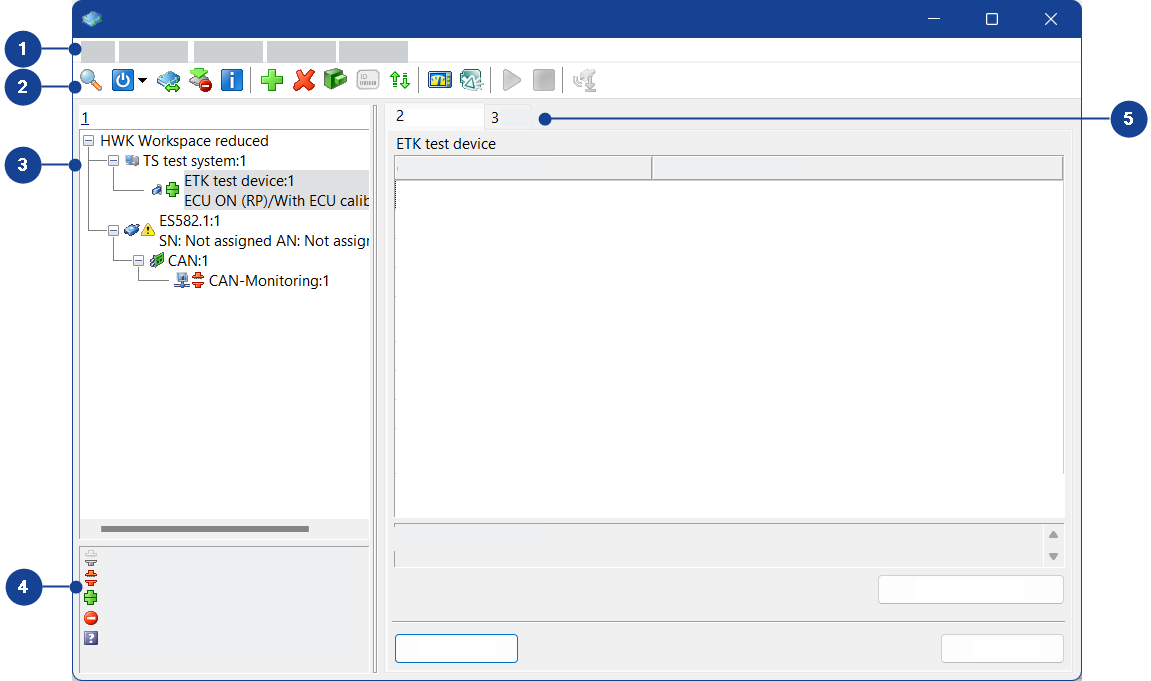
Hardware: hw Experiment: exp Window
The window title bar shows the open workspace and the experiment in use.
This window contains the following components:
The Hardware: hw Experiment: exp window contains the following menus:
This menu contains the following functions:
Open experiment environment
Opens the Experiment: exp Hardware: hw window in which you can configure the experiment environment. If the window is already open, it is brought to the foreground.
The Hardware: hw Experiment: exp window remains open.
Go to INCA Main Window
Changes to the INCA main window.
The Hardware: hw Experiment: exp window remains open.
Protocol of configuration
Opens a browser window for displaying the configuration report.
The configuration report documents all devices and their parameters in the workspace.
Note |
The configuration report of the hardware configuration editor is also included in the configuration report of the experiment environment. |
Close
Exits the hardware configuration editor.
If you make changes to the hardware configuration, these changes are accepted immediately and do not have to be saved.
This menu contains the following functions:
 Search for Hardware
Opens a dialog box for interface selection and searches for connected hardware.
If connected hardware is found, the Search for connected devices dialog box opens. You can then select the hardware with which you want to work in the current workspace.
If two or more hardware devices of the same type are found, the Hardware Mapping dialog box opens. You can accept or change the connections suggested by INCA.
 Initialize Hardware
Initializes all hardware added to the current workspace.
The ECU has to be reset before initialization. If the ECU is running, switch off the ignition.
If the memory pages of the control device are not updated, the Memory pages device window opens.
 Initializes Unconnected Devices
Initializes devices that are not yet connected.
 Hardware Mapping
Opens the Hardware Mapping dialog box, in which you can map hardware to hardware representations created in INCA.
ECU Calibration Access
Enables or prevents calibration access to the device marked in the Hardware devices list.
The calibration of the device is possible only if you have calibration access to the device.
Active Device Group
Defines whether the control device group is activated or deactivated.
An activated device group enables joint calibration of all control devices in the group. A deactivated device group enables separate calibration of each control device.
Manage Store Bits
Note |
This menu function is available only if the calibration is run via a CCP interface that supports the respective functionality. |
Requests the control device to copy the working dataset to the reference dataset. This process usually takes place later (during the switchoff logic).
 Hardware Status
Displays the current hardware status.
The hardware is initialized before its status is displayed.
 Start Measure Monitoring
Starts the measure monitoring.
 Stop Measure Monitoring
Stops the measure monitoring.
Note |
The measurement monitor can only be used with measuring devices. |
 Automatic Sensor Offset Adaption
Starts automatic sensor offset compensation.
Search for 3rd Party Hardware
If a plug-in module from a third-party manufacturer is installed, you can search for the hardware of this manufacturer here.
Check Firmware Status
Checks the firmware status of the hardware that is used by INCA and connected.
Note |
Firmware checks from within INCA require HSP V7.1.0
or higher. Firmware checks are only possible for hardware that is fully supported by HSP. |
Update Firmware
Opens the HSP Update Tool in order to check whether the firmware on the ETAS hardware devices that are connected and referenced in the INCA hardware configuration, is compatible with the current INCA version. If the firmware needs to be updated, you can start the firmware update directly from the HSP Update Tool.
Note |
This function requires HSP V7.1.0 or higher. Firmware updates are only possible for hardware that is fully supported by HSP. |
This Hardware Configuration Editor menu contains the following functions:
 Insert
Opens the Add hardware device dialog box in which you can add one or more devices to the current workspace.
 Remove
Removes the device currently marked in the Hardware devices list from the current workspace.
Note |
This is not possible with an open experiment. You must close the experiment before you can remove a device. |
Shift Up
Shifts the device currently marked in the Hardware devices list up by one position.
Shift Down
Shifts the device currently marked in the Hardware devices list down by one position.
Copy
Copies the measure device marked in the Hardware devices list to the clipboard.
Paste
Pastes the measure device from the clipboard to the Hardware devices list.
 Initialize Device
Initializes or re-initializes only the selected device.
 Change Project/Working Data
Opens the Select project and working data for device dialog box in which you can select another project and/or working dataset for the device selected in the Hardware devices list.
 Deassign Project/Working Data
Deassigns the assigned project from the device selected in the Hardware devices list. This means that only the link to the project is removed, and not the project itself.
![]() Navigate to Project in INCA Main Window
Navigate to Project in INCA Main Window
Navigates from a device to the assigned project in the Project view of the Database Manager.
Freeze Working Data
Stores the current working dataset as a new reference dataset and creates a new working dataset.
 Manage Memory Pages
Opens the Memory pages device window in which you can display, compare and edit the INCA datasets and the memory pages in the control device.
Displays the Clustering and Grouping tab.
 Read ECU ID
Reads the control device identifier.
Replace System
Replaces one system by another (e.g., at vehicle change):
- When you select a system from the sub-menu, the system that is marked in the tree view of the Hardware devices field gets replaced with the system selected from the sub-menu.
- When you select Search from the sub-menu, a dialog box is opened where you can select the host interfaces that shall be used for searching for hardware. After closing that dialog by clicking OK, INCA searches at these interfaces for the connected systems. Select a system from the list, and the system that is marked in the tree view of the Hardware devices field gets replaced with the system selected from the list.
Search/Assign XCP Slaves
If you use XCP Slave (V1.3 or later) on Ethernet, it can happen that the slave can not be found. In this case or if you want to assign another slave manually, you can search for it. For more details, see Search or Assign a XCP Slave.
Set Alias Name
Creates an internal name in the device. This helps you to distinguish between devices of the same type in the device selection dialog box.
You can also list connected devices by their assigned aliases if you are searching for connected hardware via the Windows Start menu and the ETAS program group.
Use Alias as Name
Uses the alias name as name.
Identify Device
Enables identification of devices in the vehicle by a flashing LED.
Import Measurement Scheme...
Imports measurement schemes from a CSV file to the INCA Hardware Configuration Editor.
Export Measurement Scheme...
Exports measurement schemes from the INCA Hardware Configuration Editor to a CSV file.
This menu contains the following functions:
Assign measure variables
Assigns values from the measure variable catalog to the selected measure channels (if you have specified a measure variable catalog for the measurement module).
This menu contains the following functions:
Expand all
Opens all entries in the Hardware devices list.
Collapse all
Closes all entries in the Hardware devices list.
Default Table Widths
Resets the widths of table fields on the Parameters and Channels tabs to their default values.
This menu contains the following functions:
Hotkey Assignment
Opens the Hotkey assignment for dialog box in which you can see the hotkey assignment for the hardware configuration.
Help on Current Window
Opens the help for the Hardware Configuration Editor.
Help
Opens the INCA help.
Manuals and Tutorials
Opens the directory containing the INCA manuals.
Video Tutorials
Opens an overview listing all video tutorials for INCA. You can access the videos directly from the overview.
About
Opens an information box about INCA.
Support
Shows phone numbers and e-mail addresses of the ETAS support.
Safety Advice
Displays a warning about using INCA.
The toolbar contains the following icons:
| Searches for connected hardware for INCA. If connected hardware is found, the Search for connected devices dialog box opens. You can then select the hardware with which you want to work in the current workspace. If two or more hardware devices of the same type are found, the Hardware Mapping dialog box opens. You can accept or change the connections suggested by INCA. | ||
| Checks and initializes the hardware in the current workspace. If the memory pages of the control device are not updated, the Memory pages devicewindow opens. | ||
| Indicates that all hardware is active. Via the drop-down menu, you can deactivate selected modules. | ||
| Indicates that some hardware modules are deactivated. Via the drop-down menu, you can reactivate selected modules or all modules. | ||
| Opens the Hardware Mapping dialog box, in which you can map hardware to hardware representations created in INCA. | ||
| Enables or prevents calibration access to the device marked in the Hardware devices list. | ||
| Displays the current hardware status. If the hardware has not yet been initialized, it is initialized now. | ||
| Opens the Add hardware device dialog box in which you can add one or more devices to the current workspace. | ||
| Removes the device currently marked in the Hardware devices list from the current workspace.
| ||
| Opens the Select project and working data for device dialog box in which you can select another project and/or another working dataset for the device marked in the Hardware devices list. | ||
| Reads the control device identifier. You can make these settings only if you have connected the control device via a serial interface with KWP2000 as communication protocol. | ||
| Opens the Memory pages device window in which you can display, compare and edit the INCA datasets and the memory pages in the control device. | ||
| Opens the Experiment: exp Hardware: hw window in which you can configure the experiment environment. If the window is already open, it is placed in the foreground. The Hardware: hwExperiment:exp window remains open. | ||
| Changes to the INCA main window. The Hardware: hwExperiment:exp window remains open. | ||
| Starts the measurement monitor. | ||
| Stops the measurement monitor. | ||
| Starts automatic sensor offset compensation. | ||
| Gives access to the Network Manager via the Hardware: hwExperiment:exp window. |


Contains the hardware used in the current workspace.
The icons in the hardware tree show the initialization and firmware status of the hardware.
Lists possible values of the initialization status for the hardware.
Depending on the device currently marked in the Hardware devices list, the window can have the following tabs:
To go to this tab, in the Device menu select Clustering and Grouping.
This tab contains the Clustering and Grouping table:
Name
Shows the name of the device from the Hardware devices list.
Cluster
Assigns a cluster for the device. You cluster selected control devices to switch multiple devices between working page and reference page within the INCA Experiment Environment. All devices of a cluster switch their pages together.
You can define the following:
<New cluster> | Defines a new cluster. | ||||
|---|---|---|---|---|---|
<No cluster> | Assigns no cluster. | ||||
A, B, ... | Assigns an existing cluster.
|


Note |
The control device can only be clustered
|
Leading Device
Defines the leading device. The leading device defines the initial start page of all control devices in this cluster. If the control devices in a cluster have different start pages, all ECUs will be set to the start page of the leading control device while loading the Experiment Environment.
Grouped
Shows whether this control device is grouped with another control device. Associating control devices in a group enables joint calibration of all control devices in the group.
Grouped | Groups control devices. |
|---|---|
Not grouped | Ungroups control devices. |
Note |
The control device can only be grouped if the control device is not clustered. |
This tab contains the following fields and buttons:
Name
Shows the name of the device marked in the Hardware devices list.
Parameter table
Contains parameters for the device marked in the Hardware devices list. You can change the parameter values.
Text field
Contains a brief description of the marked parameter.
![]() Additional
Additional
If this button is shown, it opens the Enhanced parameters for device dialog box in which you can view and edit other parameters.
![]() Offset Compensation
Offset Compensation
If this button is available, it corrects any measure data deviations resulting from the measurement tolerance set or the temperature flow. The deviation is subtracted from the measure value during the next measurement.
![]() Configure
Configure
Opens the hardware configuration for the selected device.
![]() Apply
Apply
Accepts changes to the parameter values for the device marked in the Hardware devices list.
![]() Reset
Reset
Undoes changes to the parameter values for the device marked in the Hardware devices list.
After changing to another device, you can no longer undo changes with Reset.
This tab contains the following fields:
Name
Shows the name of the device marked in the Hardware devices list.
Attributes table
Contains information about the device marked in the Hardware devices list.
ECU name
Shows the name of the control device if this is connected via a K-line.
This tab contains the following fields and buttons:
Name
Shows the name of the device marked in the Hardware devices list.
Channels table
Contains settings for the different channels of a device. You can change the channel settings.
Text field
Contains a brief description of the marked channel.
![]() Assign
Assign
Opens a dialog box in which you can assign measurement variables to the channels of a device.
Note |
The Assign button is active only if a measurement variable catalog is assigned to the device and at least one channel is selected. |
![]() Apply
Apply
Accepts changes to the channel settings for the device marked in the Hardware devices list.
![]() Reset
Reset
Undoes changes to the channel settings for the device marked in the Hardware devices list.
After changing to another device, you can no longer undo changes with Reset.
Note |
This tab is displayed only if you select the ES611/AD measurement device from the ES6xx device family in the Hardware devices list. |
This tab contains the following fields and buttons:
Name
Shows the name of the device marked in the Hardware devices list.
Sensor supply table
Contains parameters for the sensor supply of the sensors. You can change the parameter values.
Text field
Contains a brief description of the marked sensor supply parameter.
![]() Assign
Assign
Note |
The Assign button is active only if a measurement variable catalog is assigned to the device and at least one channel is selected. |
The Assign button open a dialog box in which you can assign measurement variables to the device channels.
![]() Apply
Apply
Accepts changes to the sensor supply parameters.
![]() Reset
Reset
Undoes changes to the sensor supply parameters.
After changing to another device, you can no longer undo changes with Reset.
Note |
This tab is displayed only if you select a CAN output device in the Hardware devices list. |
This tab contains the following fields and buttons:
Option column
| Pre-List | A list of CAN messages required by the CAN measure device for starting measurement. |
| Post-List | A list of CAN messages required by the CAN measure device for ending measurement. |
Note |
Measurement is not started/stopped until the complete pre-list/post-list has been sent. The more CAN messages in the list, and the greater the delay value of individual CAN messages, the greater the total delay. You can reduce the delay by entering a lower value for the delay in the pre-list/post-list. |
Value column
Displays the message list name of the pre-list/post-list.
Text field
Displays a brief description.
![]() Clear selected list assignment
Clear selected list assignment
Deletes the assignment between the pre-list/post-list and the selected file.
![]() Apply
Apply
Accepts selected files as pre-list/post-list.
![]() Reset
Reset
Resets the selection of pre-lists/post-lists that you defined with the Apply button.
After changing to another device, you cannot reset changes with the Reset button.
Note |
This tab is displayed only if you select a CAN output device in the Hardware devices list. |
This tab contains the following fields and buttons:
Index column
Shows the digit for hotkey-sending the CAN message list in the experiment environment.
Main list column
Displays the file names of the main lists with the CAN message lists. The main lists can be sent in the experiment environment.
Repetition option column
Defines the repetition option for each main list.
| Send once | The CAN message list is sent once only. |
| Repeat forever | The CAN message list is sent continuously. You stop sending the CAN message list manually or by closing the experiment environment. |
Text field
Displays a brief description.
![]() Clear selected list assignment
Clear selected list assignment
Deletes the assignment between the main list and the selected file.
![]() Apply
Apply
Defines the selected file as main list.
![]() Reset
Reset
Resets the selection of the main list that you defined with the Apply button.
After changing to another device, you cannot reset changes with the Reset button.
This menu contains the following functions:
Shift up main list
Moves the selected main list up one line.
Shift down main list
Moves the selected main list down one line.
Exchange main lists
Swaps selected main lists.
Note |
This function is available only if you select two main lists. To select two main lists, keep the Ctrl key pressed during selection. You cannot select more than two main lists. |
Clear selected list assignment
Deletes the assignment between the main list and the selected file.