Using a Simulink® Model
Before you can use a model for the optimization, you need to make it available in the function. Proceed as follows:
-
In the navigation pane, click Function.
The Function pane opens.
-
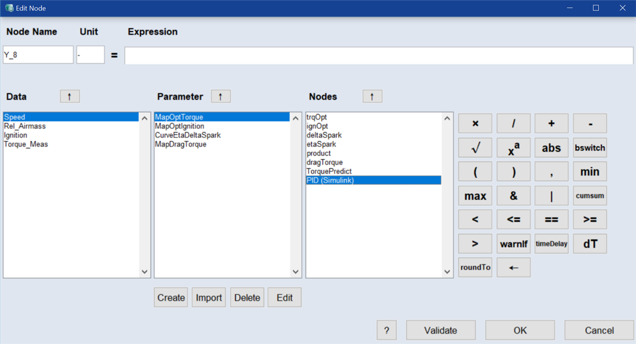
The Simulink models are available in the Nodes area of the
 Edit Node window.
 -
Insert the model in the expression.
The expression is set to %Torque%(Speed, Rel_Airmass, Ignition). In addition, the name Torque_mdl is entered in the Node Name field.
-
If desired, validate the node.
-
Click OK.
The node for the model is added to the Main Function Nodes table.
For the model output, another node named Torque_mdl.torque_Simulink_Model is created.
-
If desired, create more function nodes.
See Step 5: Build Up the Function for more information.
If you are using a Simulink model with multiple outputs, one function node is created for each model output. These nodes can be used in optimization criteria and expressions.
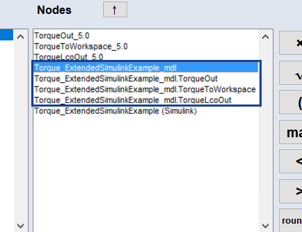
The default notation used in the Main Function Nodes table is marked in Fig. 7. The notation used in previous versions of ASCMO-MOCA (nodes Torque*_5.0 in Fig. 7) remains valid.
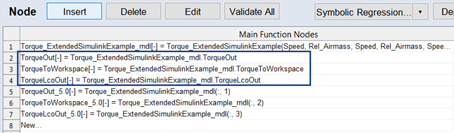
Fig. 7: Notation for a Simulink model with multiple outputs
|
Note |
|---|
|
An implementation of ASCMO-MOCA using a Simulink® model with several outputs can be found in the example project Torque_ExtendedSimulinkExample.moca in <installation>\Example\Moca directory. By default, <installation> = C:\Program Files\ETAS\ASCMO x.x. |
See also