Adding A Simulink® Model and Scripts
You can add a Simulink model, which can be selected as node in Step 5: Build Up the Function. To add a Simulink model, proceed as follows:
-
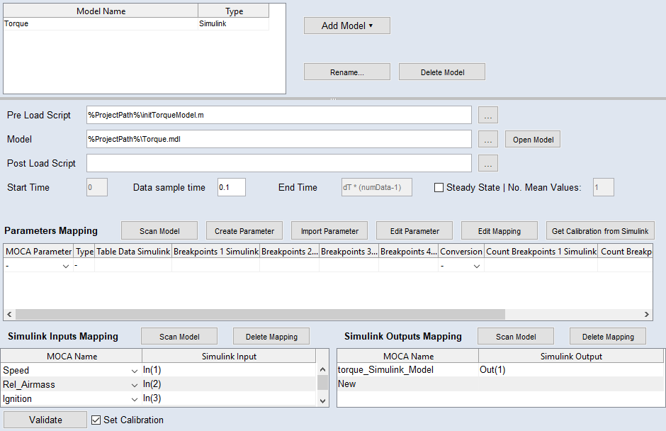
In the main working area, click Add Model and select Connect to Simulink Model.
A new line is added to the model list; additional options are displayed in the lower part of the Model Step.
-
In the Simulink Model field, enter or select (via the
 button) path and name of the Simulink model to be optimized.
This can be an *.mdl (before R2012a) or *.slx (from R2012a) Simulink model.
-
Press <Enter> or click in another field.
A warning opens if the Simulink model does not exist.
 Proceed as follows.
 -
If desired, enter or select (via the
button) path and name of an executable M-script in the Pre Load Script field.This Init script is optional and may contain a pre-calibration for the Simulink model. The pre-calibration is expected as a MATLAB workspace variable that will be assigned in the Parameters Mapping table.
-
If desired, enter or select (via the
button) path and name of another executable M-script in the Post Load Script field.This script is optional.
Note
You can use %ProjectPath% as the location. This is then automatically replaced by the current location of the ASCMO-MOCA project.