Measurement and Calibration Using UDS on Ethernet
The UDS protocol is a vendor-neutral protocol for communication between application tools and control devices. UDS on Ethernet or also referred to as Diagnostic Communication over IP.
Some parameters that are displayed in the Hardware Configuration Editor are loaded from the A2L file in advance.
Data capture from several rasters is possible with UDS. Calibration and flash programming are also possible.
Note |
Specifications for implementing UDS in ETAS calibration systems can be obtained directly from ETAS. |
INCA supports Measurement, Calibration, Diagnostics with INCA-ODX add-on, and Flashing via UDS on Ethernet according to ISO13400-2.2.
Note |
Make sure you use an A2L file with IF_DATA ASAP1B_DIAGNOSTIC_SERVICES section containing the UDS on Ethernet communication parameters according to the new AML V320. This template is available from ETAS. |
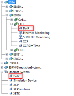
To use UDS on Ethernet with INCA or ODX-LINK, a UDS on Ethernet device has to be configured in the Hardware Configuration below an ES886 or an Ethernet System. An A2L project has also to be assigned.
Example Hardware Configuration for UDS on Ethernet
All known UDS measurement modes are supported for UDS on Ethernet. INCA uses the same UDS service sequences as for UDS CAN/CAN FD:
- Address Mode
- Block Mode
- Free Running Mode
See also
Module Parameters for UDS on Ethernet (Diagnostic Communication over IP)