Parameters for ES441 Counter and Frequency Module
The ES441 can perform the following types of measurements, each of them being configurable on its own parameters tab:
State
The active or inactive state of the input signal is determined at every sampling time. The active state is shown by the value 1 or HIGH, the inactive state by the value 0 or LOW (in normal logic). The input channels of the ES441 on which state should be measured can be specified in the measurement software (e.g. INCA).
Timer
The active or inactive duration of the input signal can be determined with every measurement channel. You can configure in INCAthe measurement software the way in which the relevant durations are determined.
Frequency
The ES441 determines frequency by measuring the time duration within a period or a cycle and then calculating f = 1 / T.
Counter
The ES441 can count edges. It is configurable if only transitions from active to inactive state, from inactive to active state, or both shall be counted. For that purpose, different configurable counting modes are available.
The following list shows the module parameters for the ES441 counter and frequency module as well as settings and information on sample rates and raster filling levels:
Shows a consecutive number.
You cannot edit this field.
This column shows the name of the hardware channel.
Note |
The hardware channel name cannot be edited. |
Select the hysteresis mode for the channel. The hysteresis mode defines two different thresholds in order to reduce noise on the signal: the upper threshold defines the transition from LOW to HIGH, the lower threshold defines the transition from HIGH to LOW.
The configuration tool offers predefined hysteresis modes (i.e. predefined threshold values) for common logics as well as the possibility to set user defined values. The hysteresis mode can be selected individually for each channel.
TTL
The threshold values will be set to 1.4 V and 1.6 V respectively.
12V Digital
The threshold values will be set to 3.0 V and 5.8 V respectively.
Hall Thresholds
The threshold values will be set to 5.0 V and 8.0 V respectively.
User Defined
You can enter the desired values for the parameters Low Threshold [V] and High Threshold [V].
The value of the Low Threshold [V] parameter depends on the selected hysteresis mode. It can only be edited manually if User Defined is set under Hysteresis.
In the User Defined mode, you
can enter any threshold value between -50 V and +50 V.
The threshold resolution is 0.1 V, i.e. you can enter values with a precision
of one decimal place.
The Low Threshold value must be smaller than the High Threshold value.
The value of the High Threshold [V] parameter depends on the selected hysteresis mode. It can only be edited manually if User Defined is set under Hysteresis.
In the User Defined mode, you
can enter any threshold value between -50 V and +50 V.
The threshold resolution is 0.1 V, i.e. you can enter values with a precision
of one decimal place.
The High Threshold value must be greater than the Low Threshold value.
Select the active state of the signal.
High
Normal logic is applied, i.e. HIGH is interpreted as active state.
Low
Inverse logic is applied, i.e. LOW is interpreted as active and HIGH as inactive state.
Select whether a PWM period starts with an active-inactive or an active-inactive edge of the signal.
Active-Inactive
The PWM period starts with an active-inactive edge. It consists of a sequence of an inactive pulse with a subsequent active pulse, i.e. a LOW value is followed by a HIGH value in normal logic.
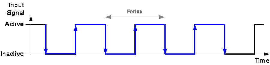
Inactive-Active
The PWM period starts with an inactive-active edge. It consists of a sequence of an active pulse with a subsequent inactive pulse, i.e. a HIGH value is followed by a LOW value in normal logic.
Enter the number of periods that each cycle consists of.
You can enter any number between 1 and 4095.
Note |
The number of periods per cycle influences value and precision
of the following signal types: |
If you would like to combine two input channels of the ES441 for signal evaluation, you need to determine which channel is to be used as the qualifying hardware channel. The qualifying hardware channel is used as a second signal input that controls the operation of counter, timer, and frequency measurement. The four input channels can be freely combined.
CH1 / CH2 / CH3 / CH4
Select the channel that will be used as qualifying hardware channel.
Selecting a channel enables additional functionality on the Timer, Frequency and Counter tab.
none
Select this option if using a qualifying hardware channel is not required.
Determine whether timeout control is to be enabled or disabled.
On
Timeout control is enabled. You can now set in the Timeout [s] column the time after which a timeout shall occur.
Once there are no state transitions within the timeout time, the system shows the following behavior:
The frequency value as well as the derived signal value are set to 0.
The duty cycle value is set 0% if the signal state is inactive; it is set to 100% if the signal state is active.
The period time is set to 0.
Off
Timeout control is disabled.
Set the period in seconds after which a timeout shall occur.
Note |
Before you can set the value for the timeout, you need to enable the timeout control in the Allowed Timeout column. |
Determine whether a glitch filter is to be used on the input stage of the hardware channel. If enabled, it will be used for simple de-bouncing and elimination of unwanted spikes.
Note |
The glitch filter removes any glitches of a maximal length of 5000 ns; at first, this causes a time delay in the hardware channel signal because the input stage has to wait for the specified filter time until it is able to decide if edges have to be accepted or discarded. These time delay effects are automatically compensated by the device. |
On
The glitch filter is enabled. You can now set in the Glitch Filter Time [ns] column the minimum duration of a pulse. Smaller pulses are ignored, only larger pulses are considered.
Off
The glitch filter is disabled.
Set the period in nano-seconds that determines whether a spike is to be regarded as unwanted and therefore filtered out by the glitch filter.
You can enter any value between 120 and 5000 ns; the resolution is 20 ns.
Note |
Before you can set the value for the glitch filter time, you need to enable the glitch filter in the Allowed Glitch Filter column. |
Enter a number to change the channel sequence.
For example, if you enter 1 for channel 3, this channel comes first. The original channel 1 is then moved to position 3.
Enter any name for the signal. The name must be unique for each signal of a module.
This column shows the name of the hardware channel.
Note |
The hardware channel name cannot be edited. |
With this parameter you can define that the states of all or some of the four hardware channels at any one time are shown together in one byte. One bit of the signal represents the state of the signal of a specifically assigned hardware channel:
Hardware Channel | Bit Position |
1 | 20 |
2 | 21 |
3 | 22 |
4 | 23 |
For that purpose, an additional entry is added to the channel list. You can set in the additional row which of the channels are to be considered.
Note |
This parameter is enabled only for the additional row. |
Double-click the parameter value in the row for the additional entry. A dialog box opens where you can set which channels are to be considered for displaying their states in one signal.
Defines the default acquisition rate necessary for your measurement task.
The acquisition rate can be selected separately for each channel of a device. It is used as default rate within the measuring environment (e.g. INCA Experiment Environment), but you can overwrite it (e.g. in INCA's Configure Variables dialog).
Note |
A large number of channels with high acquisition rate can push your system to its performance limits. If the device has only one acquisition rate, this value cannot be edited. |
Shows the physical unit for displaying the measure variable.
The unit appears in the corresponding measure windows.
Note |
The unit cannot be edited. |
Enter any comment for that signal.
Enter a number to change the channel sequence.
For example, if you enter 1 for channel 3, this channel comes first. The original channel 1 is then moved to position 3.
Enter any name for the signal. The name must be unique for each signal of a module.
This column shows the name of the hardware channel.
Note |
The hardware channel name cannot be edited. |
Shows which channel is used as qualifying hardware channel.
The qualifying hardware channel can be set on the General tab.
Define how the relevant measurement period is determined. The setting applies to all of the 3 signals of a hardware channel (active time, inactive time and period time).
Absolute
The measurement goes from the beginning of the measurement to the current sample point, i.e. the timer value continuously increases unless the reset configuration applies.
Pulse
The time measurement starts with a pulse and includes an active and inactive state in arbitrary order, i.e. the duration of the last complete pulse gets measured.
Note
If the time measurement starts with a pulse, the sum of the duration of the active and the inactive state does not necessarily equal the duration of the period because they can belong to different periods. The sum only equals the period if the pulse that is the starting point of the time measurement is also the starting point of the period.
Period
The time measurement starts at the beginning of a period, i.e. the duration of the last complete period gets measured.
Cycle
The time measurement starts at the beginning of a cycle, i.e. the duration of the last complete cycle gets measured.
Define the way in which the qualifying hardware channel (trigger channel) that is selected on the General tab is to be used for the time measurement on the hardware channel. The setting applies to all of the 3 signals of a hardware channel (active time, inactive time and period time). It can only be edited if the value Absolute is selected in the Relevant Period column.
Off
The qualifying hardware channel that is selected on the General tab will not be used for timer functionality.
inactive enable
Gate triggered behavior: The time measurement is performed on the hardware channel as long as the state on the qualifying hardware channel is inactive.
active enable
Gate triggered behavior: The time measurement is performed on the hardware channel as long as the state on the qualifying hardware channel is active.
Define when the timer will be reset to measure the next time period. The setting applies to all of the 3 signals of a hardware channel (active time, inactive time and period time). It can only be edited if the value Absolute is selected in the Relevant Period column and if the value Off is selected in the Qualifying column.
Off (free running)
The time measurement goes from the absolute beginning of the measurement to each sample point, i.e. the measured time value continuously increases.
Please note that depending on the length of the measurement, timer overflow can occur in this mode.
Sample point
The timer is reset each time a new sample is generated by the measurement module.
Inactive-active edge of Qualifier
The timer is reset each time that an inactive-active edge occurs.
This setting is available only if a qualifying hardware channel has been selected on the General tab for this hardware channel.
Active-inactive edge of Qualifier
The timer is reset each time that an active-inactive edge occurs.
This setting is available only if a qualifying hardware channel has been selected on the General tab for this hardware channel.
Defines the default acquisition rate necessary for your measurement task.
The acquisition rate can be selected separately for each channel of a device. It is used as default rate within the measuring environment (e.g. INCA Experiment Environment), but you can overwrite it (e.g. in INCA's Configure Variables dialog).
Note |
A large number of channels with high acquisition rate can push your system to its performance limits. If the device has only one acquisition rate, this value cannot be edited. |
Enter the unit according to the sensor connected and the signal to be measured.
The selected unit appears in the corresponding measure windows.
Enter the lower physical value according to the sensor used.
You can find this value in the datasheet of your sensor.
Note |
You can only enter a value if the formula used has the type "Identity" (Sensor = phys) or "Linear", i.e. the sensor connected to this channel is subject to linear calibration. However, if you use a special conversion formula, this field is empty. |
Enter the upper physical value according to the sensor used.
You can find this value in the datasheet of your sensor.
Note |
You can only enter a value if the formula used has the type "Identity" (Sensor = phys) or "Linear", i.e. the sensor connected to this channel is subject to linear calibration. However, if you use a special conversion formula, this field is empty. |
Enter the value of the lower sensor signal according to the lower physical value.
Note |
You can only enter a value if the formula used has the type "Identity" (Sensor = phys) or "Linear", i.e. the sensor connected to this channel is subject to linear calibration. However, if you use a special conversion formula, this field is empty. |
Enter the value of the upper sensor signal according to the upper physical value.
Note |
You can only enter a value if the formula used has the type "Identity" (Sensor = phys) or "Linear", i.e. the sensor connected to this channel is subject to linear calibration. However, if you use a special conversion formula, this field is empty. |
When you click into this field, an editor opens where you can create special conversion formulae.
Note |
If you use a special conversion formula, the fields of
the Phys bottom, Phys top,
Sensor bottom and Sensor top
parameters are empty. |
Enter the lower limit of the expected physical measurement range.
This value is used together with the values of the Phys bottom, Sensor bottom and Formula parameters to calculate the amplification factor.
The highest amplification factor possible is selected to ensure that none of the connected channels is overloaded.
Enter the upper limit of the expected physical measurement range.
This value is used together with the values of the Phys top, Sensor top and Formula parameters to calculate the amplification factor.
The highest amplification factor possible is selected to ensure that none of the connected channels is overloaded.
Shows the lower physical limit of the measurement range actually possible for this channel.
This value is determined by the values of the Phys bottom, Sensor bottom and Formula parameters as well as by the actual measurement range of the module.
You cannot edit this field.
Shows the upper physical limit of the measurement range actually possible for this channel.
This value is determined by the values of the Phys top, Sensor top and Formula parameters as well as by the actual measurement range of the module.
You cannot edit this field.
Enter any comment for that signal.
Advantage of the procedure:
- No additional error by integer division
Disadvantages of the procedure:
- A possible division by zero in the calibration software must be considered,
- The Timeout function is not available for the frequency.
The accuracy of the calculated frequency values depends on different influencing factors, e.g. the selected frequency mode.
See detailed information on accuracy for further information on influencing factors and tips on how to avoid large deviations.
Theoretical Error During Frequency Measurement
The ES441 measures the period duration with the accuracy of the internal timebase of 20 ns. The frequency to be determined is calculated and corresponds to the reciprocal value of the period duration:
f = 1 / T
Due to the integer division in the ES441 module, the result of frequency measurement is issued as an integer value with a resolution of 0.02 Hz (quantization). The jitter of the internal timebase can be ignored and is excluded from the examination of the measurement error.
The following is true, with the frequency f and n periods per cycle:
x = f / n
The theoretical error e(x) is thus:
ε(x) = x * 20 ns + 0.02 Hz / x
In the case of low frequencies, measurement accuracy is mainly governed by the error of the integer division. In the case of high frequencies, the resolution of the internal timebase of the ES441 has a greater influence on measurement accuracy.
Increasing Measurement Accuracy with Low Frequencies
When determining low frequencies, the result can be inaccurate due to the integer calculations. This error can be avoided by measuring the period duration instead of the frequency and calculation of the reciprocal value in the calibration software on the PC (either as a formula in the A2L file or as a calculated signal).
Increasing Measurement Accuracy with High Frequencies
When determining high frequencies, the result can be inaccurate due to measurement errors in the determination of the period duration by the internal timebase. This error can be avoided or diminished if the frequency is measured over one cycle instead of over the period duration. The proportion of the measurement error which can be attributed to the internal timebase is then distributed to the n periods of the cycle.
When measuring a cycle of frequency fc with n periods instead of a period of the frequency fp, the following is true for the measurement result:
fp = n * fc
The measurement error can be very high when measuring very high frequencies or very short periods as the period duration of the signal to be measured and the resolution of the internal timebase of the ES441 are of comparable dimension. This is why, with high frequencies, the frequency should be determined using the cycle duration and not the period duration.
Enter a number to change the channel sequence.
For example, if you enter 1 for channel 3, this channel comes first. The original channel 1 is then moved to position 3.
Enter any name for the signal. The name must be unique for each signal of a module.
This column shows the name of the hardware channel.
Note |
The hardware channel name cannot be edited. |
Shows which channel is used for deriving the direction of the movement.
The qualifying hardware channel can be set on the General tab.
Define how the relevant frequency is determined. The setting applies to all of the 3 signals of a hardware channel (period, frequency and duty time).
Frequency over Period
The frequency is derived from the length of the period (reciprocal of period).
Note
When you are measuring very high frequencies and therefore very short periods, the deviation can be comparatively high because the period length might get close to the step size of the resolution of the internal time base. For that reason, it is recommended to measure frequencies over cycle lengths instead of periods whenever you are measuring high frequencies.
Frequency over Cycle (rpm)
The frequency is derived from the length of the cycle (in rounds per minute).
Define the way in which the qualifying hardware channel (trigger channel) that is selected on the General tab is to be used for the frequency measurement on the hardware channel. The qualifying hardware channel can be used to derive the direction of the movement, which is coded as a sign to the frequency value. The sign is controlled either by the state (Sign1, Sign2) or the phase relation (Sign3, Sign4).
The setting can only be edited for signals of the type "Frequency"; it cannot be edited for signals of the types "Duty Cycle" and "Period".
Off
The qualifying hardware channel that is selected on the General tab will not be used for frequency measurement.
Sign1: active+/inactive-
The frequency is positive while the state on the qualifying hardware channel is active, and it is negative while the state on the qualifying hardware channel is inactive.
Sign2: active-/inactive+
The frequency is negative while the state on the qualifying hardware channel is active, and it is positive while the state on the qualifying hardware channel is inactive.
Sign3: equal+/unequal-
The frequency is positive if the state on the qualifying hardware channel is equal to the state on the main input channel, and it is negative if the states are unequal.
Sign4: equal-/unequal+
The frequency is negative if the state on the qualifying hardware channel is equal to the state on the main input channel, and it is positive if the states are unequal.
Defines the default acquisition rate necessary for your measurement task.
The acquisition rate can be selected separately for each channel of a device. It is used as default rate within the measuring environment (e.g. INCA Experiment Environment), but you can overwrite it (e.g. in INCA's Configure Variables dialog).
Note |
A large number of channels with high acquisition rate can push your system to its performance limits. If the device has only one acquisition rate, this value cannot be edited. |
Enter the unit according to the sensor connected and the signal to be measured.
The selected unit appears in the corresponding measure windows.
Enter the lower physical value according to the sensor used.
You can find this value in the datasheet of your sensor.
Note |
You can only enter a value if the formula used has the type "Identity" (Sensor = phys) or "Linear", i.e. the sensor connected to this channel is subject to linear calibration. However, if you use a special conversion formula, this field is empty. |
Enter the upper physical value according to the sensor used.
You can find this value in the datasheet of your sensor.
Note |
You can only enter a value if the formula used has the type "Identity" (Sensor = phys) or "Linear", i.e. the sensor connected to this channel is subject to linear calibration. However, if you use a special conversion formula, this field is empty. |
Enter the value of the lower sensor signal according to the lower physical value.
Note |
You can only enter a value if the formula used has the type "Identity" (Sensor = phys) or "Linear", i.e. the sensor connected to this channel is subject to linear calibration. However, if you use a special conversion formula, this field is empty. |
Enter the value of the upper sensor signal according to the upper physical value.
Note |
You can only enter a value if the formula used has the type "Identity" (Sensor = phys) or "Linear", i.e. the sensor connected to this channel is subject to linear calibration. However, if you use a special conversion formula, this field is empty. |
When you click into this field, an editor opens where you can create special conversion formulae.
Note |
If you use a special conversion formula, the fields of
the Phys bottom, Phys top,
Sensor bottom and Sensor top
parameters are empty. |
Enter the lower limit of the expected physical measurement range.
This value is used together with the values of the Phys bottom, Sensor bottom and Formula parameters to calculate the amplification factor.
The highest amplification factor possible is selected to ensure that none of the connected channels is overloaded.
Enter the upper limit of the expected physical measurement range.
This value is used together with the values of the Phys top, Sensor top and Formula parameters to calculate the amplification factor.
The highest amplification factor possible is selected to ensure that none of the connected channels is overloaded.
Shows the lower physical limit of the measurement range actually possible for this channel.
This value is determined by the values of the Phys bottom, Sensor bottom and Formula parameters as well as by the actual measurement range of the module.
You cannot edit this field.
Shows the upper physical limit of the measurement range actually possible for this channel.
This value is determined by the values of the Phys top, Sensor top and Formula parameters as well as by the actual measurement range of the module.
You cannot edit this field.
Enter any comment for that signal.
Enter a number to change the channel sequence.
For example, if you enter 1 for channel 3, this channel comes first. The original channel 1 is then moved to position 3.
Enter any name for the signal. The name must be unique for each signal of a module.
This column shows the name of the hardware channel.
Note |
The hardware channel name cannot be edited. |
Shows which channel is used as qualifying hardware channel.
The qualifying hardware channel can be set on the General tab.
You can combine any two channels of the ES441 for counter measurement and define with this parameter how these channels are combined. As a prerequisite, you must have selected a qualifying hardware channel on the General tab for the corresponding input channel.
Standard
The desired counter mode can be individually configured by setting the values in the columns Relevant Edge/Counts, Qualifying and Counter Reset.
X1
The qualifying hardware channel acts as a control and defines whether the counter will be incremented or decremented. The level of the qualifying signal directly defines the direction:
With each rising edge (inactive to active) of the input signal, the counter is incremented if the qualifying signal is inactive, and it is decremented if the qualifying signal is active.
X2
The qualifying hardware channel acts as a control and defines whether the counter will be incremented or decremented.
With each rising edge (inactive to active) and each falling edge (active to inactive) of the input signal, the counter is incremented if the levels of both signals are unequal, and it is decremented if the levels of both signals are equal.
The phase shift of the main input signal and the qualifying signal determines the counting direction.
X4
The qualifying hardware channel is used as a second counter input and works together with the main input channel.
The main input channel channel and its assigned second signal on the qualifying hardware channel are analyzed as equal channels. Both edges of the signals at the two channels are evaluated according to different rules. The phase difference of the signals of the two channels determines the count direction:
With each rising or falling edge (inactive to active or active to inactive) of the main input signal or the secondary signal on the qualifying hardware channel, the counter is incremented or decremented.
Rules for evaluating signal edges at the main input channel:
The counter is incremented when the signal edges at the main input channel and the signal at the qualifying hardware channel do not have an identical state, and it is decremented when the signal edges at the main input channel and the signal at the qualifying hardware channel have an identical state.
Rules for evaluating signal edges at the qualifying hardware channel:
The counter is incremented when the signal edges at the qualifying hardware channel and the signal at the main input channel have an identical state, and it is decremented when the signal edges at the qualifying hardware channel and the signal at the main input channel do not have an identical state.
This counter mode provides a higher resolution than the X2 counter mode as both edges of both channels are evaluated.
Up-Down
The counter is incremented at each rising edge of the main input signal and decremented at each rising edge of the signal on the qualifying hardware channel.
Define what items are to be counted. The setting can only be edited if the value Standard is selected in the Counter Mode column.
Active-Inactive
Counts all active-inactive edges.
Inactive-Active
Counts all inactive-active edges.
Both
Counts all active-inactive and inactive-active edges.
Cycle
Counts all cycles.
Define the way in which the qualifying hardware channel (trigger channel) that is selected on the General tab is to be used for the counter on the hardware channel. The setting can only be edited if the value Standard is selected in the Counter Mode column.
Off
The qualifying hardware channel that is selected on the General tab will not be used for counter functionality.
Gate1: active enable/inactive disable
Gate triggered behavior: The edges at the main input channel are only counted when the qualifying hardware channel is active.
Gate2: active disable/inactive enable
Gate triggered behavior: The edges at the main input channel are only counted when the qualifying hardware channel is inactive.
Up/Down1: equal--/unequal++
The counter is decremented if the state on the qualifying hardware channel is equal to the state on the main input channel, and it is incremented if the states are unequal.
Up/Down2: equal++/unequal--
The counter is incremented if the state on the qualifying hardware channel is equal to the state on the main input channel, and it is decremented if the states are unequal.
Up/Down3: active++/inactive--
The counter is incremented while the state on the qualifying hardware channel is active, and it is decremented while the state on the qualifying hardware channel is inactive.
Up/Down4: active--/inactive++
The counter is decremented while the state on the qualifying hardware channel is active, and it is incremented while the state on the qualifying hardware channel is inactive.
Define when the counter will be reset in order to restart counting.
Off (free running)
The count goes from the absolute beginning of the measurement to each sample point, i.e. the counter value continuously increases.
Note
Please note that depending on the length of the measurement, counter overflow can occur in this mode.
Sample point
The counter is reset each time a new sample is generated by the measurement module.
Inactive-active edge of Qualifier
The counter is reset each time that an inactive-active edge occurs on the qualifying hardware channel.
Note
This setting is not available for all counter configurations. It is only available if on the General tab, a qualifying hardware channel has been selected for the corresponding input channel and in the Counter Mode column, the value Standard is selected and in the Qualifying column, if one of the values Off, Gate1 or Gate2 is selected .
Active-inactive edge of Qualifier
The counter is reset each time that an active-inactive edge occurs on the qualifying hardware channel.
Note
This setting is not available for all counter configurations. It is only available if on the General tab, a qualifying hardware channel has been selected for the corresponding input channel and in the Counter Mode column, the value Standard is selected and in the Qualifying column, if one of the values Off, Gate1 or Gate2 is selected .
Defines the default acquisition rate necessary for your measurement task.
The acquisition rate can be selected separately for each channel of a device. It is used as default rate within the measuring environment (e.g. INCA Experiment Environment), but you can overwrite it (e.g. in INCA's Configure Variables dialog).
Note |
A large number of channels with high acquisition rate can push your system to its performance limits. If the device has only one acquisition rate, this value cannot be edited. |
Enter the unit according to the sensor connected and the signal to be measured.
The selected unit appears in the corresponding measure windows.
Enter the lower physical value according to the sensor used.
You can find this value in the datasheet of your sensor.
Note |
You can only enter a value if the formula used has the type "Identity" (Sensor = phys) or "Linear", i.e. the sensor connected to this channel is subject to linear calibration. However, if you use a special conversion formula, this field is empty. |
Enter the upper physical value according to the sensor used.
You can find this value in the datasheet of your sensor.
Note |
You can only enter a value if the formula used has the type "Identity" (Sensor = phys) or "Linear", i.e. the sensor connected to this channel is subject to linear calibration. However, if you use a special conversion formula, this field is empty. |
Enter the value of the lower sensor signal according to the lower physical value.
Note |
You can only enter a value if the formula used has the type "Identity" (Sensor = phys) or "Linear", i.e. the sensor connected to this channel is subject to linear calibration. However, if you use a special conversion formula, this field is empty. |
Enter the value of the upper sensor signal according to the upper physical value.
Note |
You can only enter a value if the formula used has the type "Identity" (Sensor = phys) or "Linear", i.e. the sensor connected to this channel is subject to linear calibration. However, if you use a special conversion formula, this field is empty. |
When you click into this field, an editor opens where you can create special conversion formulae.
Note |
If you use a special conversion formula, the fields of
the Phys bottom, Phys top,
Sensor bottom and Sensor top
parameters are empty. |
Enter the lower limit of the expected physical measurement range.
This value is used together with the values of the Phys bottom, Sensor bottom and Formula parameters to calculate the amplification factor.
The highest amplification factor possible is selected to ensure that none of the connected channels is overloaded.
Enter the upper limit of the expected physical measurement range.
This value is used together with the values of the Phys top, Sensor top and Formula parameters to calculate the amplification factor.
The highest amplification factor possible is selected to ensure that none of the connected channels is overloaded.
Shows the lower physical limit of the measurement range actually possible for this channel.
This value is determined by the values of the Phys bottom, Sensor bottom and Formula parameters as well as by the actual measurement range of the module.
You cannot edit this field.
Shows the upper physical limit of the measurement range actually possible for this channel.
This value is determined by the values of the Phys top, Sensor top and Formula parameters as well as by the actual measurement range of the module.
You cannot edit this field.
Enter any comment for that signal.
Enter a number to change the channel sequence.
For example, if you enter 1 for channel 3, this channel comes first. The original channel 1 is then moved to position 3.
Shows the name of the channel.
Defines how the output voltages can be selected:
predefined
You can choose between different preset supply voltages provided to the sensor connected to this channel.
user defined
The output voltages you define are used. If you enter output voltages which are below or above the minimum or maximum value respectively, the software automatically replaces your entry by the closest possible value.
Defines the output voltage that supplies connected sensors.
The ES441 supports fixed sample rates (measurement rasters). Several sample rates can be assigned simultaneously to each input channel. A maximum of eight different sample rates can be used for each ES441 module.
The sample rates that have already been selected on the parameter tabs in the Rate columns are displayed in the combo boxes in the Sample Rate/Filling Level group; they are disabled (grayed out). In the remaining combo boxes that are not disabled, you can select additional sample rates.
If you are using INCA as your measurement and application tool, these sample rates will be offered as predefined rasters in INCA. Faster rasters cannot be selected in the INCA Variable Selection dialog.
It is not possible to measure all signals with the highest sample rate. Therefore, the filling level shows the load of the module, thereby indicating whether it is possible to measure all signals with the rates that are defined on the parameter tabs.
Note |
Filling Levels of more than 100 % are not allowed. |