Hardware specifications
Ambient Conditions
|
Item |
Characteristics |
|
Operating temperature range |
- 40 °C to +110 °C - 40 °F to +230 °F |
|
Storage temperature range(without packaging) |
0 °C to +50 °C +32°F to +122 °F |
|
Max. relative humidity |
95% |
|
Max. altitude |
max. 5000 m/ 16400 ft |
|
Degree of contamination |
2 |
|
Protection rating (IEC 60529) |
Determined by installation in ECU |
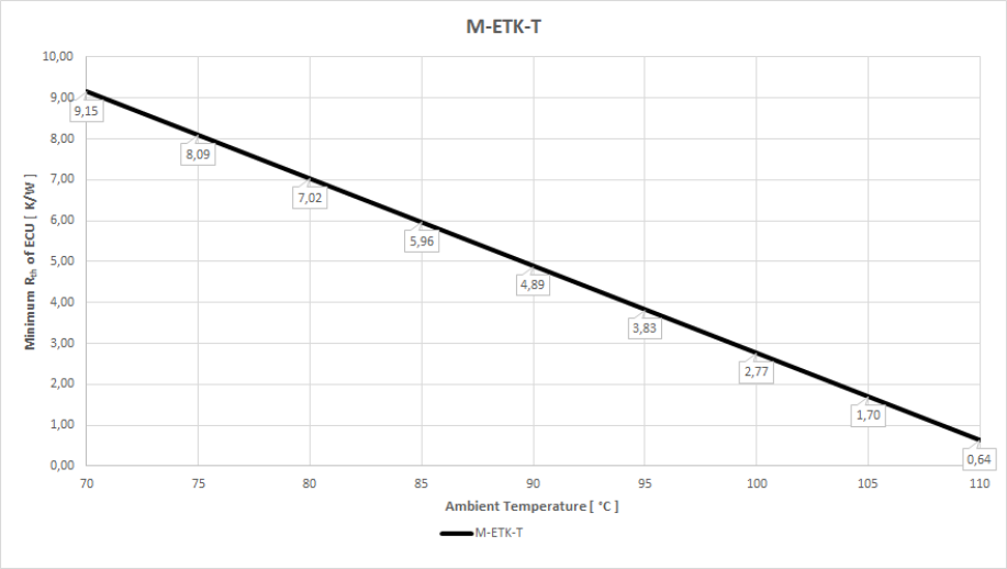
Inside the ECU housing the max. temperature is specified with 110 °C, still air. Outside of the ECU the max. ambient temperature is assumed to be 85 °C at 1 m/s airflow. The power dissipation of the M-ETK is typically 5 W.
|
T ambiente (°C) |
Minimum Rth Heatspreader Ambient [K/W] |
|
70 |
9,15 |
|
75 |
8,09 |
|
80 |
7,02 |
|
85 |
5,96 |
|
90 |
4,89 |
|
95 |
3,83 |
|
100 |
2,77 |
|
105 |
1,70 |
|
110 |
0,64 |
Electrical Data
|
Parameter |
Symbol |
Condition |
Min |
Typ |
Max |
Unit |
|
Permanent power supply |
UBatt |
Vehicle usage 1) |
6 |
12 |
36 |
V |
|
[all values ±0%] |
||||||
|
Cranking voltage |
UBatt |
< 3 seconds |
3 |
|
|
V |
|
Standby current |
ISTBY |
UBatt = 12 V; ECU off; |
8 |
24 |
40 |
mA |
|
Operating current |
IBatt |
UBatt = 12 V; |
150 |
250 |
350 |
mA |
|
Power dissipation |
PBatt |
UBatt = 12 V; |
1.8 |
3 |
4.2 |
W |
|
Power dissipation |
PBatt |
UBatt = 12 V; |
2.8 |
4 |
5.2 |
W |
|
Fuse in the ETK UBatt supply line. Only required if the power supply or ECU is not protected accordingly. |
MINI, 2 A 58 V DC (Littelfuse 0997002.WXN) |
|||||
|
Overvoltage category |
|
II | ||||
|
1) The M-ETK implements reverse voltage protection in the same range and may be used only with central load dump protection. 24 V vehicles require UBatt disturbing pulse reduction to 12 V vehicle system. 12 V vehicles don’t require special disturbing pulse reductions. |
||||||
|
Note |
|---|
|
The M-ETK will accept power supply voltage dips (for additional details of 3 V low voltage operation, see ISO standard 16750). |
Maximum Inrush Current
It is highly recommended that the M-ETK be connected to a permanent power supply. When this is not possible, or the M-ETK must be powered off and back on in short intervals, time is required to reactivate the inrush limiting circuit of the M-ETK.
If the time between powering the ETK off and on is less than 40 seconds a high current peak can occur. If the above-mentioned fuse is used, this inrush current will not trigger the fuse. If other protection mechanisms are in place, the inrush current must be considered in the ECU design.
|
Time Between Powering Off and On |
Inrush Current Pulse ( UBatt = 12 V) |
|
> 40 s |
700 mA / 5 ms |
|
< 40 s |
18 A / 60 µs |
Power Supply Pin Assignment
|
Pin |
Signal |
Direction |
Comment |
|
1 |
VDDSTBY |
Output |
Permanent power supply of ECU DAP Interface, 3.3 V |
|
2 |
VDDPSTBY (1.30 V supply) |
Output |
Permanent power supply of ECU EDRAM, 1.30 V |
|
3 |
GND |
Input |
Power Ground |
|
4 |
CAL_WAKEUP |
Output |
Switch to UBatt. ECU wake-up signal |
|
5 |
Ubatt2 |
Input |
Vehicle battery |
|
6 |
Ubatt1 |
Input |
Vehicle battery |
Microcontroller Interface (adapter dependent)
|
Parameter |
Symbol |
Condition |
Min |
Typ |
Max |
Unit |
|
ECU Standby RAM Output Voltage |
VDDSTBY |
max 500 mA load |
0.94 |
1 |
1.04 |
V |
|
VDDPSTBY |
VDDPSTBY |
max 80 mA load |
3.14 |
3.3 |
3.46 |
V |
|
Cal_Wakeup |
CAL_WAKEUP |
UBatt = 6 - 36 V; |
UBatt-1V |
|
UBatt |
V |
|
ECU Power Supply Supervision Voltage |
VDDP
|
ECU on |
2.67 |
2.77 |
2.89 |
V |
|
ECU off |
2.44 |
2.56 |
2.89 |
V |
||
|
abs. max. |
|
|
5.50 |
|
||
|
IDDP |
VDDP 3.3 V |
|
|
800 |
mA |
|
|
ECU Standby RAM Supervision Voltage |
VDDSTBY /VDDSTBY_SENSE IDDSTBY |
VDDSTBY |
0.86 |
0.89 |
0.92 |
V |
|
VDDSTBY ¯ |
0.85 |
0.88 |
0.91 |
V |
||
|
VDDSTBY 1.0 V |
|
|
50 |
mA
|
Test Characteristics
|
Parameter |
Symbol |
Condition |
Min |
Typ |
Max |
Unit |
|
Start-up Time 1 1) |
tReset1 |
UBatt = 12 V |
0 |
5 |
10 |
ms |
|
Start-up Time 2 1) |
tReset2 |
UBatt = 0 V 12 V |
|
20 |
|
s |
|
|
||||||
SWD Timing Characteristics
The M-ETK supports the 2-pin SWD mode: one data pin (direction via protocol), one clock pin.
|
Parameter |
Symbol |
Value SR6X7[ns] |
Value SR6P7 [ns] |
Comment |
|---|---|---|---|---|
|
SWCLK Clock Period (typ.) |
tCLK |
14.31) |
8.02) |
ETK --> Target |
|
SWDIO Set-Up Time |
tSU |
4.0 |
2.3 |
ETK --> Target |
|
SWDIO Hold Time |
tH |
1.5 |
2.3 |
ETK --> Target |
|
SWDIO Clock-to-Out Time |
tCO |
12.4 |
11.5 |
Target --> ETK |
|
SWDIO Output Hold Time |
tOH |
4.3 |
3 |
Target --> ETK |
|
SWDIO data unstable window |
|
|
3 |
|
|
1) : @ 70 MHz SWD Clock Frequency 2): @ 125 MHz SWD Clock Frequency |
|
|
||
Aurora Trace Timing Parameter
|
Parameter |
Value |
Unit |
Signal Impedance [Ohm] |
|
Clock |
100 |
MHz |
100 (differential) |
|
Data rate DATA[3...0] |
3.125 |
Gbit/s |
100 (differential) |
Electrical Characteristics
ECU Interface Connector SWD Interface
|
Signal |
Pin Type |
VOL |
VOH |
VOH |
VIL |
VIH |
VIH |
Leakage current |
Additional load by ETK 1) (typ) [pF] |
|
SWCLK (TCK) |
XO1) |
0.4 |
2.8 |
3.3 |
- |
- |
5.5 |
+705 / +495 |
35 |
|
SWDIO (TMS) |
IXO1) |
0.4 |
2.8 |
3.3 |
0.8 |
2 |
5.5 |
-43 / -18 |
35 |
|
RESERVED (TDO) |
IXO1) |
0.4 |
2.8 |
3.3 |
0.8 |
2 |
5.5 |
+10 / -10 |
35 |
|
RESERVED (TDI) |
XO1) |
0.4 |
2.8 |
3.3 |
- |
2 |
5.5 |
+10 / -10 |
35 |
|
/TRST |
XO2) |
0.6 |
2.4 |
3.3 |
- |
- |
5.5 |
-705 / -569 |
21 |
|
/RESETOUT |
IXOD3) |
0.7 |
- |
- |
0.8 |
2 |
5.5 |
+21 / -20 |
21 |
|
/PORESET |
IXOD3) |
0.7 |
- |
- |
0.8 |
2 |
5.5 |
+21 / -20 |
25 |
|
WDGDIS |
XO2)) |
0.5 |
2.4 |
3.3 |
- |
- |
5.5 |
+10 / -10 |
21 |
|
Pin Type: |
|||||||||
|
1) max 16mA |
|||||||||
ECU Interface Connector JTAG Interface
|
Signal |
Pin Type |
VOL |
VOH |
VOH |
VIL |
VIH |
VIH |
Leakage current |
Additional load by ETK 1) (typ) [pF] |
|
SWCLK (TCK) |
XO1) |
0.4 |
2.8 |
3.3 |
- |
- |
5.5 |
+705 / +495 |
35 |
|
SWDIO (TMS) |
IXO1) |
0.4 |
2.8 |
3.3 |
0.8 |
2 |
5.5 |
-43 / -18 |
35 |
|
RESERVED (TDO) |
IXO1) |
0.4 |
2.8 |
3.3 |
0.8 |
2 |
5.5 |
+10 / -10 |
35 |
|
RESERVED (TDI) |
XO1) |
0.4 |
2.8 |
3.3 |
- |
2 |
5.5 |
+10 / -10 |
35 |
|
/TRST |
XO2) |
0.6 |
2.4 |
3.3 |
- |
- |
5.5 |
-705 / -569 |
21 |
|
/RESETOUT |
IXOD3) |
0.7 |
- |
- |
0.8 |
2 |
5.5 |
+21 / -20 |
21 |
|
/PORESET |
IXOD3) |
0.7 |
- |
- |
0.8 |
2 |
5.5 |
+21 / -20 |
25 |
|
WDGDIS |
XO2)) |
0.5 |
2.4 |
3.3 |
- |
- |
5.5 |
+10 / -10 |
21 |
|
Pin Type: |
|||||||||
|
1) max 16mA |
|||||||||
ECU Interface Connector Pin Assignment
|
Pin |
JTAG Mode |
SWD Mode |
Direction |
Comment |
|---|---|---|---|---|
|
1 |
GND |
GND |
Power |
Signal Ground |
|
2 |
TCK |
SWCLK |
Output |
depending interface mode |
|
3 |
/TRST |
/TRST |
Output |
depending interface mode |
|
4 |
TDO |
RESERVED(TDO) |
Bidir |
depending interface mode |
|
5 |
TMS |
SWDIO |
Bidir |
depending interface mode |
|
6 |
TDI |
RESERVED(TDI) |
Bidir |
depending interface mode |
|
7 |
WDGDIS |
WDGDIS |
Output |
Watchdog disable Signal |
|
8 |
VDDP (Sense) |
VDDP (Sense) |
Input |
Sense for Switched power supply of ECU (ignition) |
|
9 |
/RESETOUT |
/RESETOUT |
Bidir |
ECU Reset signal (open drain) for Reset assertion and supervision |
|
10 |
/PORESET |
/PORESET |
Bidir |
ECU Power On Reset signal (open drain) for Reset assertion and supervision |
ECU Interface Connector Aurora Trace
|
Signal |
Pin Type |
VID (min) [mV] |
VID (max) [mV] |
VOD (max) [mV] |
|
Clock-P/-N |
XO |
- |
- |
490 |
|
DATA[3...0] |
I |
140 |
1250 |
- |
|
Pin type: |
||||
|
Signal |
Pin Type |
VOL (max) [V] |
VOH (min) [V] |
VOH (max) [V] |
VIL (max) [V] |
VIH (min) [V] |
VIH (max) [V] |
Leakage current |
Additional |
|
AUR_RESERVED |
XO 1) |
0.6 |
2.4 |
3.1 |
- |
- |
6.5 |
+159 / +99 |
24 |
|
Pin Type: |
|||||||||
|
1) max 24 mA |
|||||||||
ECU Interface Connector Aurora Trace Pin Assignment
|
Pin |
Signal |
Direction |
Comment |
|
1 |
GND |
- |
Signal Ground |
|
2 |
GND |
- |
Signal Ground |
|
3 |
Data1-N |
Input |
Aurora Data Lane 1 |
|
4 |
Data0-P |
Input |
Aurora Data Lane 0 |
|
5 |
Data1-P |
Input |
Aurora Data Lane 1 |
|
6 |
Data0-N |
Input |
Aurora Data Lane 0 |
|
7 |
GND |
- |
Signal Ground |
|
8 |
GND |
- |
Signal Ground |
|
9 |
Data2-P |
Input |
Aurora Data Lane 2 |
|
10 |
GND |
- |
Signal Ground |
|
11 |
Data2-N |
Input |
Aurora Data Lane 2 |
|
12 |
Clock-N |
Output |
Aurora Clock |
|
13 |
GND |
- |
Signal Ground |
|
14 |
Clock-P |
Output |
Aurora Clock |
|
15 |
Data3-N |
Input |
Aurora Data Lane 3 |
|
16 |
GND |
- |
Signal Ground |
|
17 |
Data3-P |
Input |
Aurora Data Lane 3 |
|
18 |
- |
- |
not connected |
|
19 |
GND |
- |
Signal Ground |
|
20 |
AUR_Reserved |
Output |
do not use |
Mechanical Data
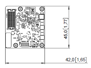
The reference measure for all drawings is millimeters.
|
Item |
Dimension [mm] |
Dimension [in] |
|
Length |
45.00 |
1.77 |
|
Width |
42.00 |
1.65 |
|
Height |
10.85 |
0.43 |
Weight
|
Item |
Weight[g] |
|
M-ETK-T1 (incl Heatspreader) |
30 |
|
M-ETK-AB1.0 |
10 |
|
Total |
40 |
Hole/Drilling Pattern for the ECU-housing

Four screws M2
Recommended drilling diameter for the M2 screws is 2.2 mm.
|
Dimension [mm] |
Tolerance [mm] |
Dimension [in] |
Tolerance [in] |
|
23 |
+/- 0.20 |
0.91 | 0.07874 |
|
28 |
+/- 0.20 |
1.11 | 0.07874 |
|
39 |
+/- 0.20 |
1.54 | 0.07874 |