Measurement
The M-ETK provides comprehensive capabilities for real-time measurement of internal ECU variables (signals, parameters, memory contents). This is crucial for understanding the ECU's behavior, validating software functions, and supporting calibration activities. The system supports various measurement techniques to cater to different microcontroller (µC interface) architectures, debug interfaces, and performance requirements.
Core Concepts of Data Acquisition
All measurement involves two fundamental steps:
-
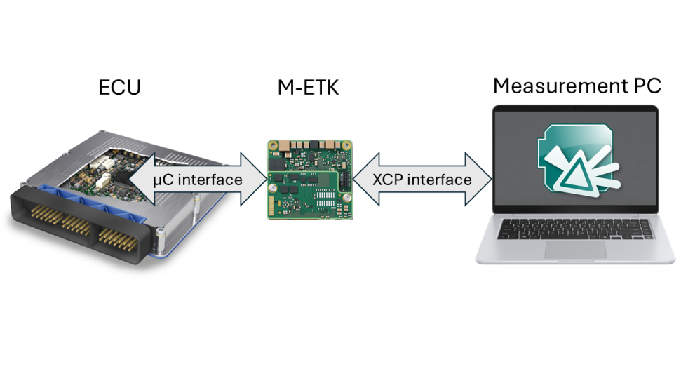
Data Sampling (µC interface): The point in time when a signal’s value is captured from the ECU’s memory.
-
Data Transmission (XCP interface): The process of sending the captured data from the ECU/M-ETK to your computer.
There are two primary modes for sampling this data:
-
Polling Mode: The measurement tool continuously requests data from the ECU. This is simple to implement but is less efficient, as each data point requires a separate request. It can create a high load on the serial interface and the data may not be consistent, because it is not measured synchronous to it's creation time within the ECU.
-
Event-Triggered / DAQ Mode: The ECU is configured to autonomously sample and transmit data when a specific event occurs (a "trigger"). This is highly efficient as it allows for blocks of data (known as DAQ lists) to be sent in bursts, significantly reducing bus load and improving performance. This is the preferred mode for most measurement tasks.
Data Acquisition Methods
The M-ETK supports several data acquisition methods, each with different characteristics, benefits, and resource requirements.
|
Method |
Description |
Key Advantages |
Key Considerations |
|---|---|---|---|
|
Timer-Triggered Polling |
The M-ETK periodically reads signal values directly from the ECU's RAM at a user-defined interval. |
Very easy to set up. |
No signal consistency; as values can change while being read. |
|
Triggered Direct Measurement (TDM) |
The ECU's software sends a trigger to the M-ETK, which then reads the required signals directly from their memory addresses. |
Low impact on ECU runtime. |
Signal consistency is not guaranteed if timing is not managed carefully. |
|
Display Table (DISTAB) |
When triggered, the ECU copies a predefined list of signals into a dedicated, consistent data block. The M-ETK reads this entire block in a single operation. |
Guaranteed data consistency for all signals within the block. |
Requires a small amount of ECU CPU time and RAM to copy the data. |
|
Trace-Based Measurement (T2R/T2P) |
A hardware trace unit on the microcontroller automatically captures every data change in a monitored memory window. This provides the most detailed measurement possible. |
Perfect data consistency. |
T2P offers the highest performance by streaming data directly over a fast dedicated interface, while T2R writes the data to a µC internal buffer memory and provides it via the debug interface |
The Role of Triggers and Interfaces
-
Triggers: A trigger is an event that initiates a data measurement. Triggers are highly configurable and can be based on timers (e.g., every 10ms), software events within the ECU code, or specific hardware signals. This ensures that data is captured at the precise moment it is needed. To ensure data validity even when the ECU is off, the uC supports a standby supply for the RAM used for the Working Page from the M-ETK.
-
Interfaces: The measurement performance heavily depends on the physical connection between the M-ETK and the ECU. The M-ETK supports a wide range of microcontroller interfaces, from standard serial interfaces (like JTAG or DAP) for basic measurement to high-speed trace interfaces (like Aurora) for the most demanding data acquisition tasks. This versatility allows the M-ETK to be a cost-effective and high-performance solution for a variety of use cases.