Mounting and placement
Mounting the M-ETK into the ECU Housing
|
NOTICE |
|---|
|
Damage to the electronics due to potential equalization The cables' shield may be connected to the housing, the ground or the ground for the product's power supply. If there are different ground potentials in the test setup, equalizing currents can flow between the products via the cables' shield. Take account of different electric potentials in your test setup and take appropriate measures to prevent equalizing currents. |
Thermal Connection Requirements
To ensure proper operation of the M-ETK over the specified temperature range, the M-ETK must be mounted to the ECU metal housing. This enables thermal dissipation of the electronic components used on the M-ETK to the ECU housing.
|
Note |
|---|
|
To avoid overheating of the M-ETK the connection to the ECU housing following requirements for thermal resistance must be met:
If the value of ECU housing thermal conductivity cannot be achieved, additional cooling structures, e.g. heat sinks, should be applied. |
For additional details on thermal dissipation, see chapter Technical specifications.
Mounting Material
To mount the M-ETK + M-ETK-AB1.0 to the ECU housing several materials are required:
-
M-ETK
-
M-ETK-AB1.0 Adapter
incl. M2 x 7 Spacers
incl .M2 x 4 cylinder head screws
-
ECU metal housing
-
Heat conductive paste (or foil)
-
Four screws M2
-
cylinder head, countersunk-, self-sealing screw
-
length depending on the ECU project:
min. 7.95mm + wall thickness ECU housing
max. 9.6mm + wall thickness ECU housing
-
-
Two nuts M2
-
Thread locking fluid
-
Screwdriver T4, T6
Mounting Steps
To mount the M-ETK into the ECU housing several mounting steps are required:
Preparing the ECU Housing
-
Drill four holes in the ECU housing.
For further information on the dimensions of the drill holes, see Technical specifications.
-
Add the opening for the Cable gland for the CBAM435 cable.
Preparing the M-ETK
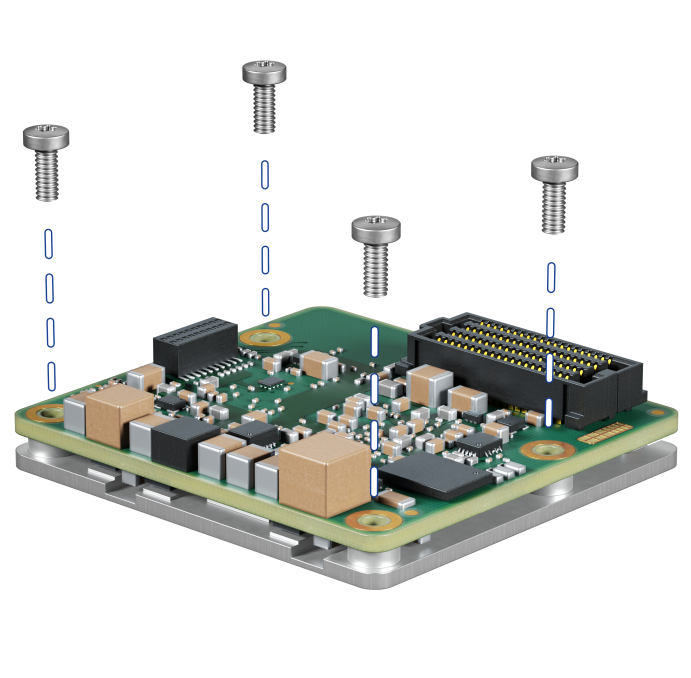
-
Remove the four screws from the M-ETK. The screws are only a transport lock for the heatspreader.
-
Apply a thin layer of heat conductive paste (or foil) to the bottom side of the M-ETK heatspreader.
Attaching the M-ETK to the ECU Housing
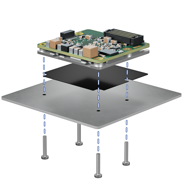
-
Place the M-ETK with the thermal paste (or foil) into the ECU housing and fasten it from the outside using four M2 screws, length depending on the metal housing.
-
Insert the screws into the holes in the ECU housing.
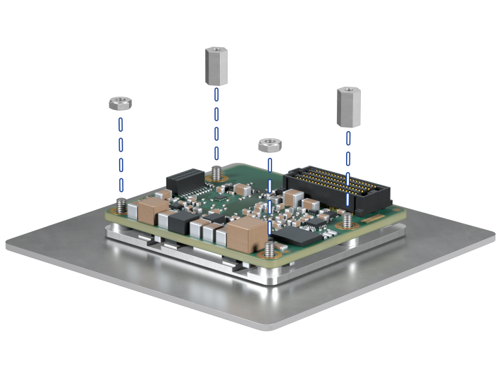
-
Add the M2 nuts and spacers. Use thread locking fluid.
Connect the adapter
_725x543.png)
-
Connect the M-ETK-AB1.0 Adapter into the M-ETK.
-
Screw it in place with the two M2 x 4 screws. Use thread locking fluid.
Connection to the ECU
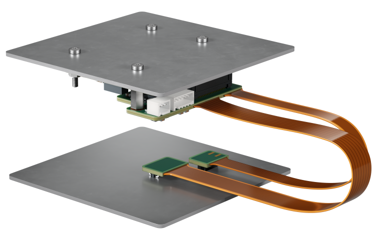
-
Plug the two connectors onto the ECU circuit board.
-
Connect the powercable and CBAM435 cable.
-
Close the ECU housing. Heatspreader Screws.