Connectors
|
Note |
|---|
|
All connections are shown with view of the module interfaces. |
Terminal assignment of sockets
Connection "7-29 V"
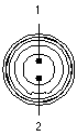
Fig. 5-2 Connection "7-29 V"
|
Pin |
Signal |
Description |
|---|---|---|
|
1 |
UBATT+ |
Supply voltage, positive |
|
2 |
Ground |
Ground |
"FE-HOST" connection

Fig. 5-3 "FE-HOST" connection
|
Pin |
Signal |
Description |
|---|---|---|
|
1 |
- |
Reserved |
|
2 |
- |
Reserved |
|
3 |
- |
Reserved |
|
4 |
RX+ |
Receiving data, positive |
|
5 |
TX- |
Transmitting data, negative |
|
6 |
RX- |
Receiving data, negative |
|
7 |
- |
Reserved |
|
8 |
TX+ |
Transmitting data, positive |
"GE-HOST" connection

Fig. 5-4 "GE-HOST" connection
|
Pin |
Signal |
Description |
|---|---|---|
|
1 |
BI_DA+ |
|
|
2 |
BI_DA- |
|
|
3 |
BI_DB+ |
|
|
4 |
BI_DC+ |
|
|
5 |
BI_DC- |
|
|
6 |
BI_DB- |
|
|
7 |
BI_DD+ |
|
|
8 |
BI_DD- |
|
|
9 |
N.C. |
Not connected |
|
10 |
N.C. |
Not connected |
Connections "ETH1" to "ETH6"

Fig. 5-5 Connections "ETH1" to "ETH6"
|
Pin |
Signal |
Description |
|---|---|---|
|
1 |
UBATT+ |
Supply voltage, positive |
|
2 |
UBATT+ |
Supply voltage, positive |
|
3 |
UBATT- |
Supply voltage, negative |
|
4 |
RX+ |
Receiving data, positive |
|
5 |
TX- |
Transmitting data, negative |
|
6 |
RX- |
Receiving data, negative |
|
7 |
UBATT- |
Supply voltage, negative |
|
8 |
TX+ |
Transmitting data, positive |