Mounting and placement
|
WARNING |
|---|
|
Risk of injury due to inadequate fastening
|
Fastening the module on a carrier system
The ES600.2 has a robust metal housing that is fitted with non-slip plastic feet. The module can be screwed onto a carrier system for fastening in a vehicle or lab. The screw threads for fixing the module are part of the housing and are easily accessible.
To fix the housing of the ES600.2, proceed as follows:
- Remove the plastic feet at the underside of the module. To do so, push a blunt screwdriver between the housing bottom and the plastic foot.
- Pry off the plastic foot.
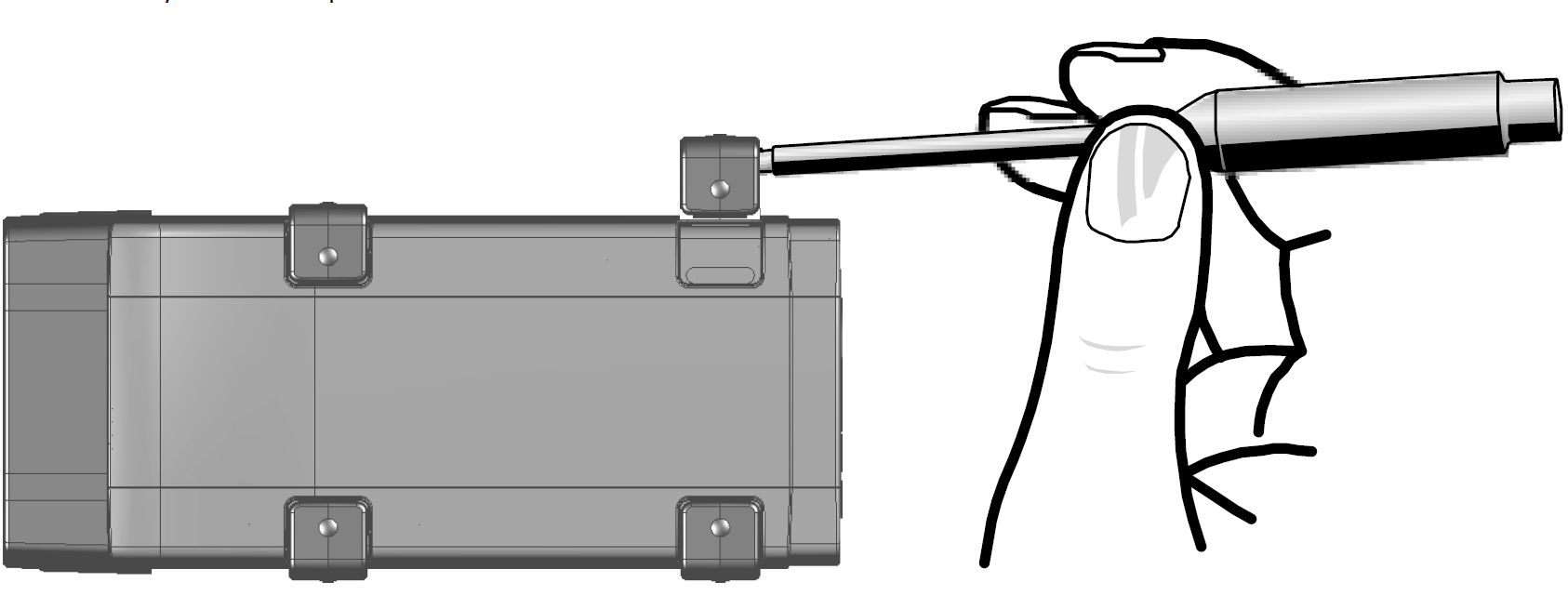
Fig. 1: Fig. 4-1 Prying off the plastic foot
A screw thread becomes visible under the plastic foot. The threads for fixing the module are located at the underside of the housing.
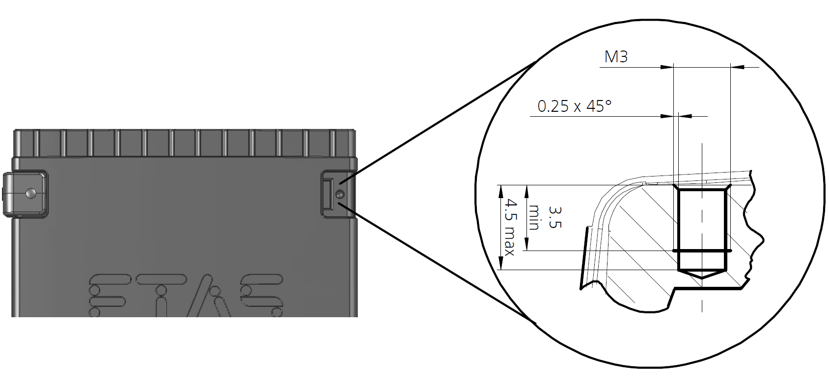
Fig. 2: Fig. 4-2 Blind hole with thread
|
Note |
|---|
|
Screw the module onto your carrier system using exclusively M3 cylinder screws and a max. torque of 0.8 Nm. The screw-in depth in the blind hole of the housing measures max. 3 mm. |
Mechanically connecting several modules
Because of the use of ETAS system housings, the Synchronization and Power Management Module can also be connected with modules of the ETAS compact series, for example ES59x, ES6xx and ES910. They can be combined into larger blocks using the supplied T-connectors.
Underneath the ES600.2, you can attach an additional module of the ETAS compact series. To do so, remove the four plastic feet at the corresponding side of the device and install the supplied T-connectors in their place.
To mechanically connect several modules, proceed as follows:
- Remove the four plastic feet at the underside of the ES600.2 to be able to fasten an additional module.
- Remove the four plastic feet on the corresponding side of the second module.
- Turn the locks of the T-connectors crosswise to the longitudinal axis of the connectors.
- Click two connectors into the installation openings at one longitudinal side of the first module.
- Click the second module into the two T-connectors.
- Turn the locks of the T-connectors a quarter turn. This locks the connection of the two modules.
- Click the two other T-connectors into the installation openings at the opposite longitudinal side of the device.
- Lock these connectors, too.
- To stack additional modules and fasten them above each other, repeat the process with the next module.

Fig. 3: Fig. 4-3 Connecting the ES600.2 with another module