Graphical overview of elements
Front side
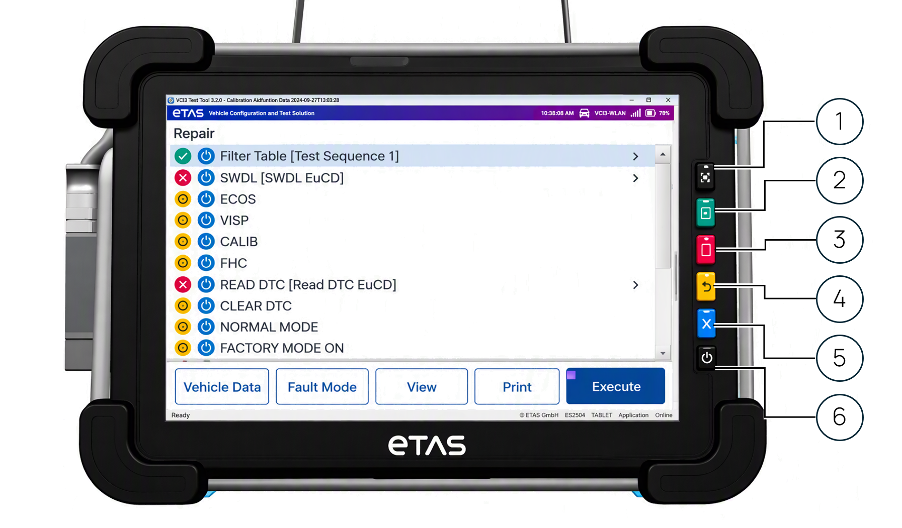
|
Fig. |
Connection Key |
Description |
|---|---|---|
|
1 |
Top black |
Activate bar code scanner |
|
2 |
Green |
OK |
|
3 |
Red |
Not OK |
|
4 |
Yellow |
Return |
|
5 |
Blue |
Abort |
|
6 |
Bottom black |
Power on/off |
Right side
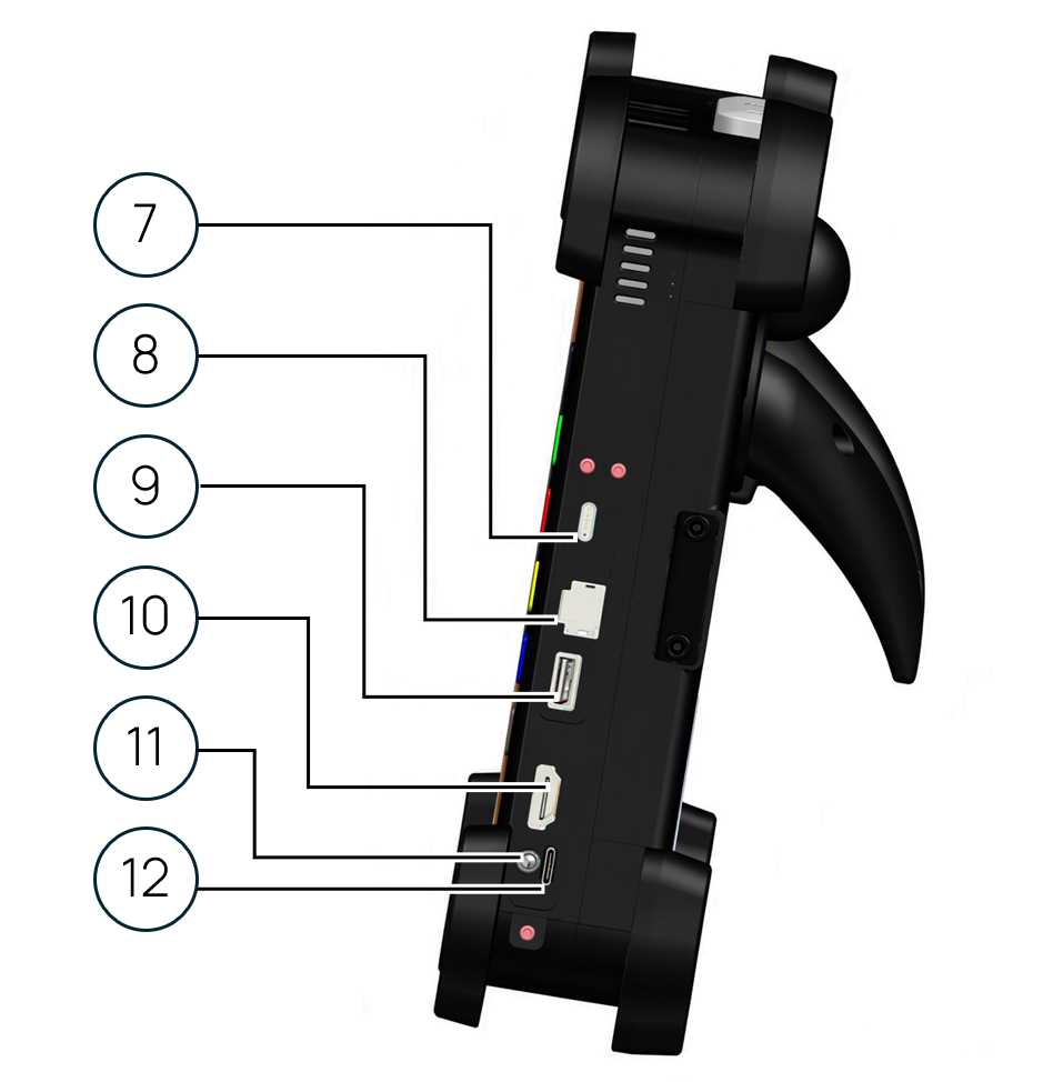
|
Fig. |
Connection |
Description |
|---|---|---|
|
7 |
USB-C |
USB-C cable |
|
8 |
Ethernet (LAN) |
RJ45 cable |
|
9 |
USB-A (3.0) |
USB-A cable |
|
10 |
HDMI |
HDMI cable |
|
11 |
Audio jack |
3.5 mm audio plug (headphones) |
|
12 |
SIM card slot |
SIM card |
Left side
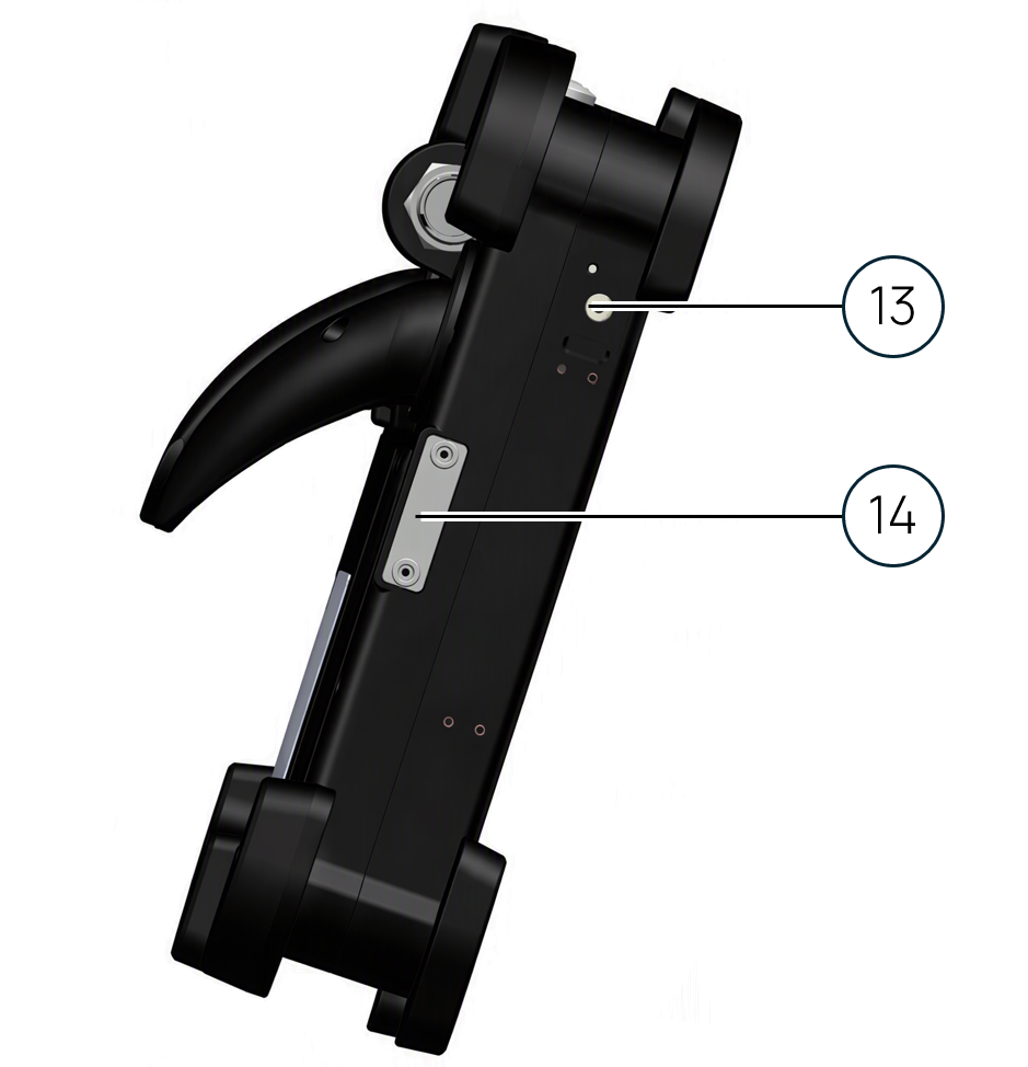
|
Fig. |
Connection |
Description |
|---|---|---|
|
13 |
External power jack |
External power supply cable |
|
14 |
DLC docking pegs |
Magnetic feature to secure DLC when not in use |
Rear side
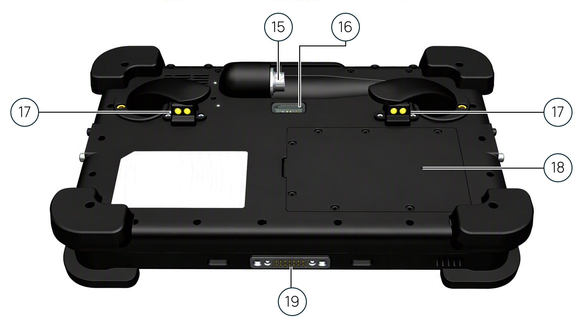
|
Fig. |
Connection |
Description |
|---|---|---|
|
15 |
DLC connector |
Vehicle-specific DLC cable for CAN/CAN FD connection and charging |
|
16 |
VIN scanner |
Scanner for VIN (remove protective cover before use) |
|
17 |
Charging pins |
Interface for charging station / DLC cable connection for diagnostic communication and charging from the vehicle |
|
18 |
Battery compartment cover |
Cover is secured with seven screws |
|
19 |
Engineer docking station pins |
Interface to the engineer docking station for charging and USB connection |
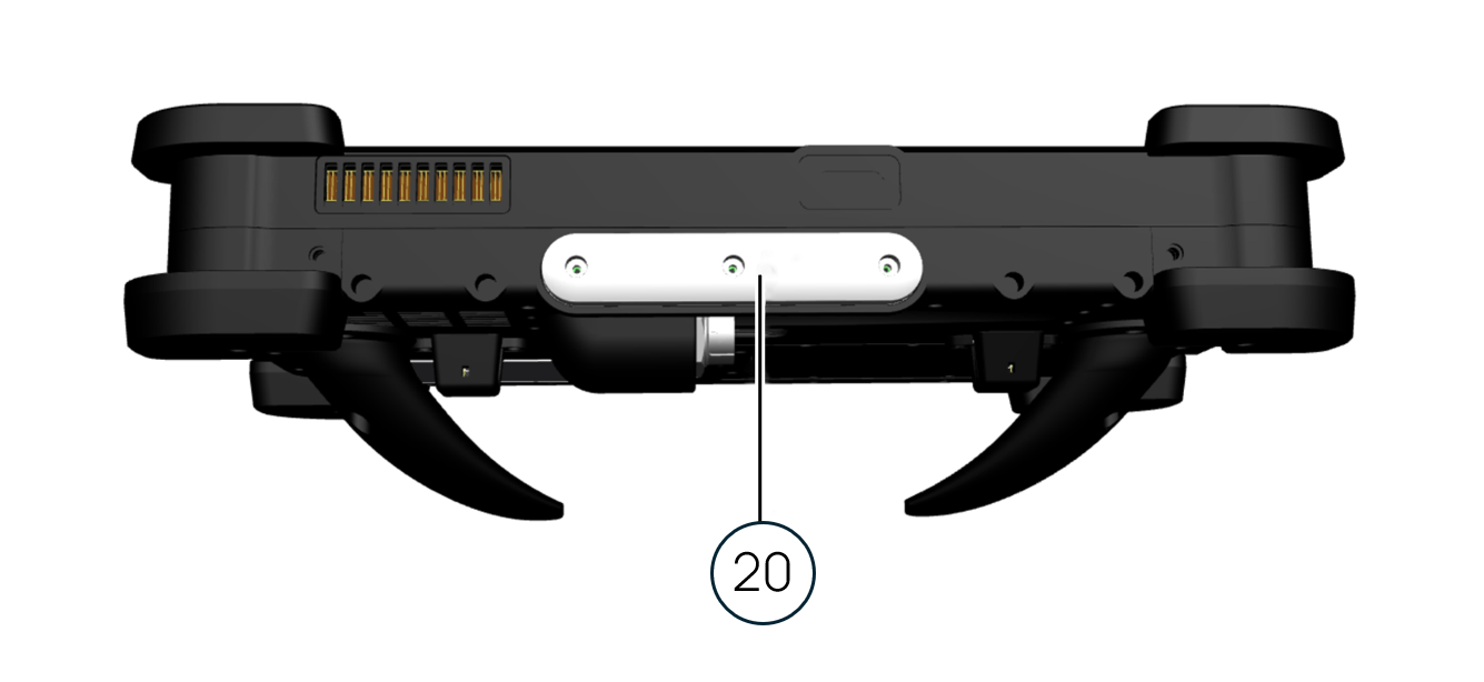
Top side
|
Fig. |
Connection |
Description |
|---|---|---|
|
20 |
LED status indicator and IrDA Transceiver |
Indicates charging and sequence status / receives IrDA beacon wake-up and location data |