Battery, charging and power states
Installation of the battery pack
The ES2504 is shipped with the battery pack uninstalled. Tools are provided in the carton for user installation.
|
WARNING |
|---|
|
Fire Hazard The product contains a lithium battery. Damaged lithium batteries may cause heat, fire or short circuits. In the event of battery damage, the product must be taken out of service immediately, and ETAS Support must be contacted: www.etas.com/hotlines. Damaged or defective lithium batteries must under no circumstances be transported via standard parcel courier or air freight services. |
|
NOTICE |
|---|
|
Care should be taken not to touch the main printed circuit board assembly within the unit when the battery is removed. ESD protective measures must be observed. |
1. Align the locating lugs on the battery pack at a 45° angle with the mating features on the main unit.
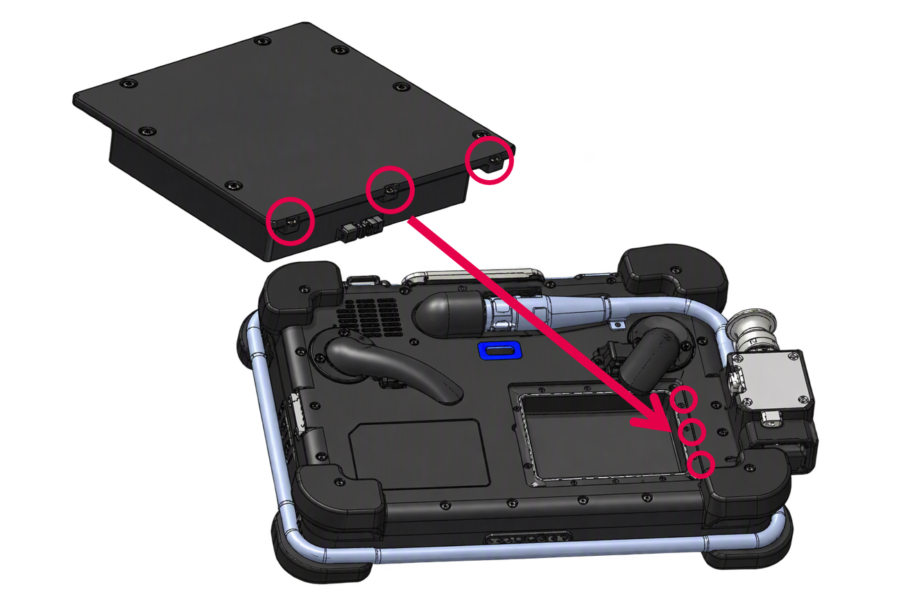
2. Ensuring the electrical contacts of the battery pack are connected to their counterparts on the main unit, insert the battery pack as shown.
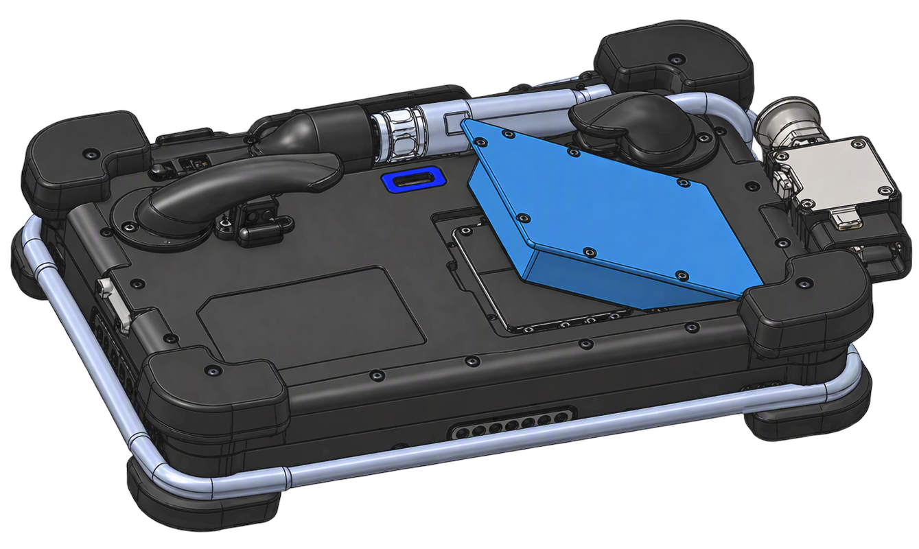
3. Secure the battery pack with the seven M2.5 fixings and tool provided.
Initial charging
Before first use: Charge the ES2504 to at least 90%. For optimized charging, use approved ETAS accessories or connect directly to the vehicle’s DLC port.
Switching on
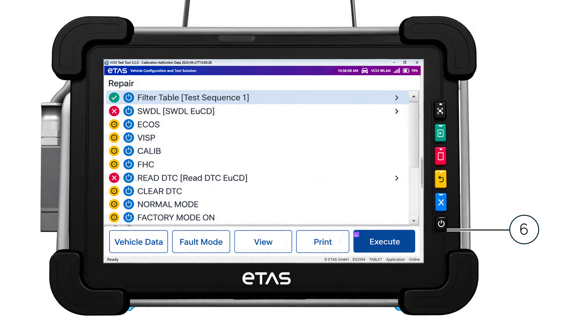
The ES2504 can be switched on by pressing the Power Button (6) located on the front keypad for 3 seconds.
After switching on, the unit will boot to Microsoft Windows™ desktop or a dedicated application according to the product’s software configuration.
Power states
The following table describes how to enter and exit the different the power states of the ES2504.
|
ATTENTION |
|---|
|
A power button press of longer than 15 seconds will, on release, cause a forced hardware shutdown. This feature is not recommended in regular use. It should only be used for essential recovery if the recommended shutdown methods are unresponsive. When using this function, there is a possibility that the data on the SSD drive could become corrupted. |
|
Power State (ACPI) |
Screen Status |
Power Button Press Duration [sec] |
Action |
Note |
|
Power off (G2 / S5) |
off |
< 3 |
N/A |
|
|
off |
> 3 |
Power on |
|
|
|
Power on (S0) |
on |
< 3 |
N/A |
|
|
on |
3 -> 10 |
Enter sleep/hibernate |
According to power settings |
|
|
off |
3 -> 10 |
Screen on |
|
|
|
on |
10 -> 15 |
Windows shut down |
|
|
|
off |
10 -> 15 |
Windows shut down |
|
|
|
on |
> 15 |
Forced hardware shutdown |
|
|
|
Sleep/hibernate (S1-S4) |
off |
3 -> 10 |
Resume |
According to power settings |
Advanced Configuration and Power Interface (ACPI) States Supported
|
State |
Description |
|
G0/S0/C0 |
Full On: CPU operating. Individual devices may be shut to save power. The different CPU operating levels are defined by Cx states. |
|
GO/S0/Cx |
Cx state: CPU manages C-states by itself and can be in low power state. |
|
G1/S3 |
Suspend-To-RAM (STR): The system context is maintained in system DRAM, but power is shut to non-critical circuits. Memory is retained, and refreshes continue. All external clocks are shut off; RTC clock and internal clocks are still running. |
|
G1/S4 |
Suspend-To-Disk (STD): The context of the system is maintained on the disk. All power is then shut to the system except to the logic required to resume. Externally appears same as S5 but may have different wake events. |
|
G2/S5 |
Soft Off: System context not maintained. All power is shut except for the logic required to restart. A full boot is required when waking. |
|
G3 |
Mechanical OFF: System context not maintained. All power shut except for the RTC. No “Wake” events are possible because the system does not have any power. This state occurs if the user removes the batteries, turns off a mechanical switch, or if the system power supply is at a level that is insufficient to power the “waking” logic. When system power returns the transition will depend on the state just prior to the entry to G3. |