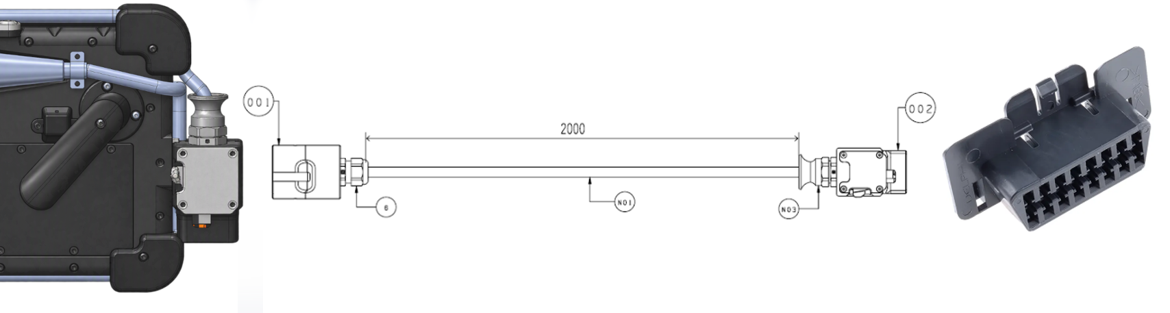
DLC cable and connector
The cable and connector are used for data connection and power supply from a vehicle diagnostic port.
|
Note |
|---|
|
Care should be taken not to touch the main printed circuit board assembly within the unit when the battery is removed. ESD protective measures must be observed. |
Installation of the DLC cable
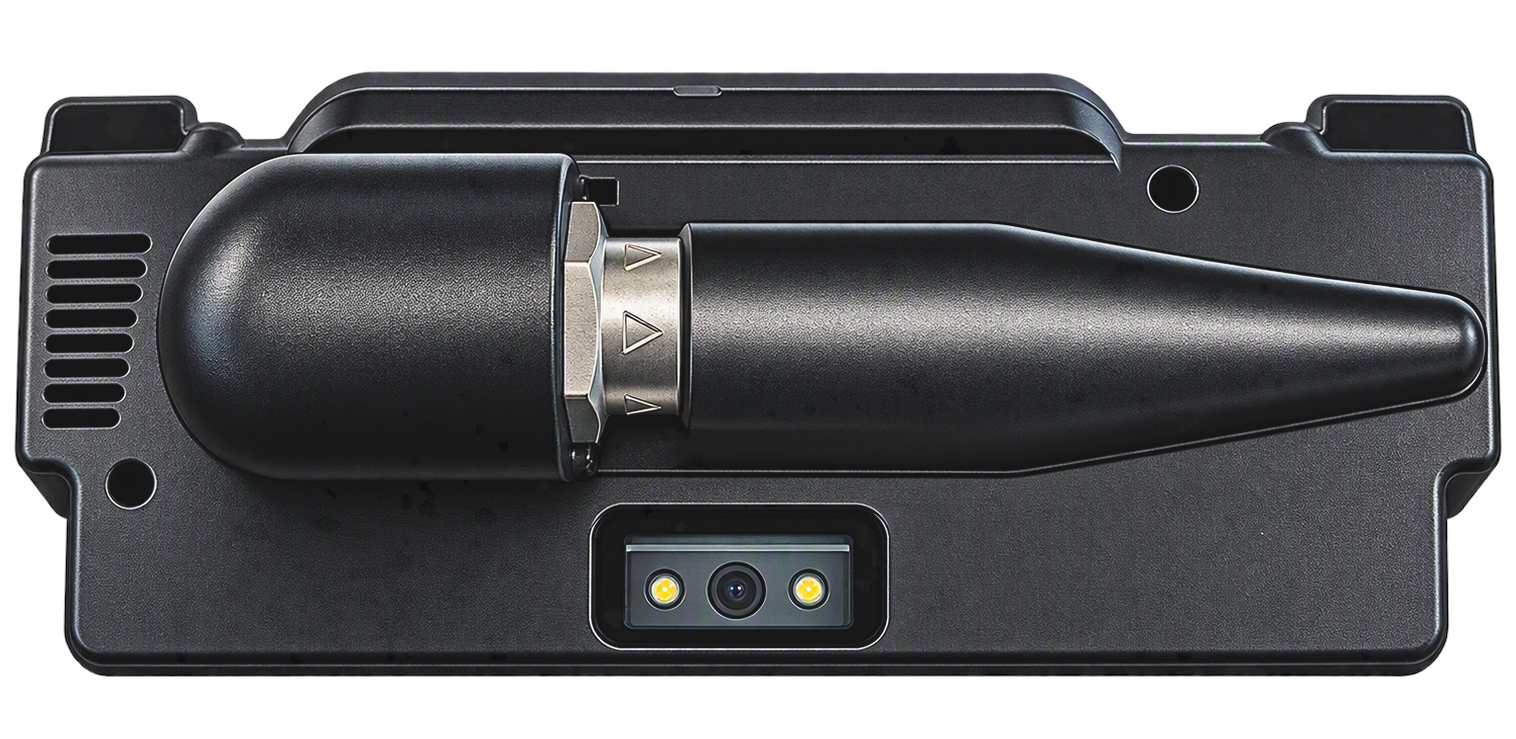
1. Align the arrow on the DLC cable connector with the arrow on the mating connector on the ES2504.
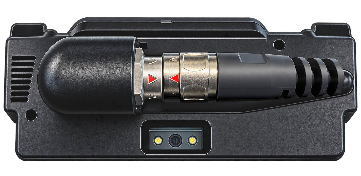
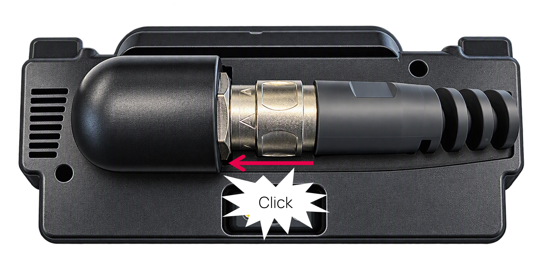
2. Push the DLC cable connector onto the mating part until it clicks and latches into place.
When not in use, the main DLC cable can be wrapped around the ES2504. For convenient cable wrapping, use the dedicated slots in the corner bumpers and secure the connector using the magnetic mounts on either side of the case (14).
On select models, an indicator LED is integrated into the DLC plug. This LED lights up as soon as power is supplied by the vehicle, confirming a successful connection.
Some models have a sprung latch (A) which engages with a corresponding feature on the vehicle connector. A release button (B) is provided which must be depressed and held in while withdrawing the connector. The connector can be mated without pressing the button.
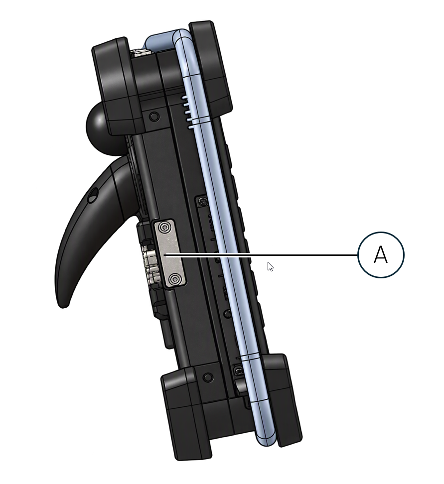
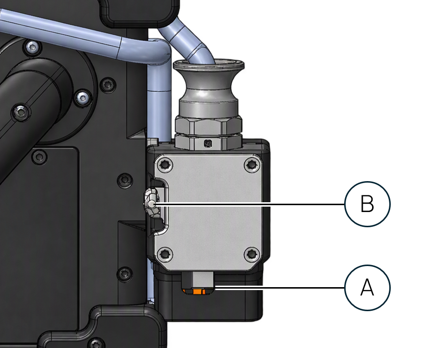
Removal of the DLC cable
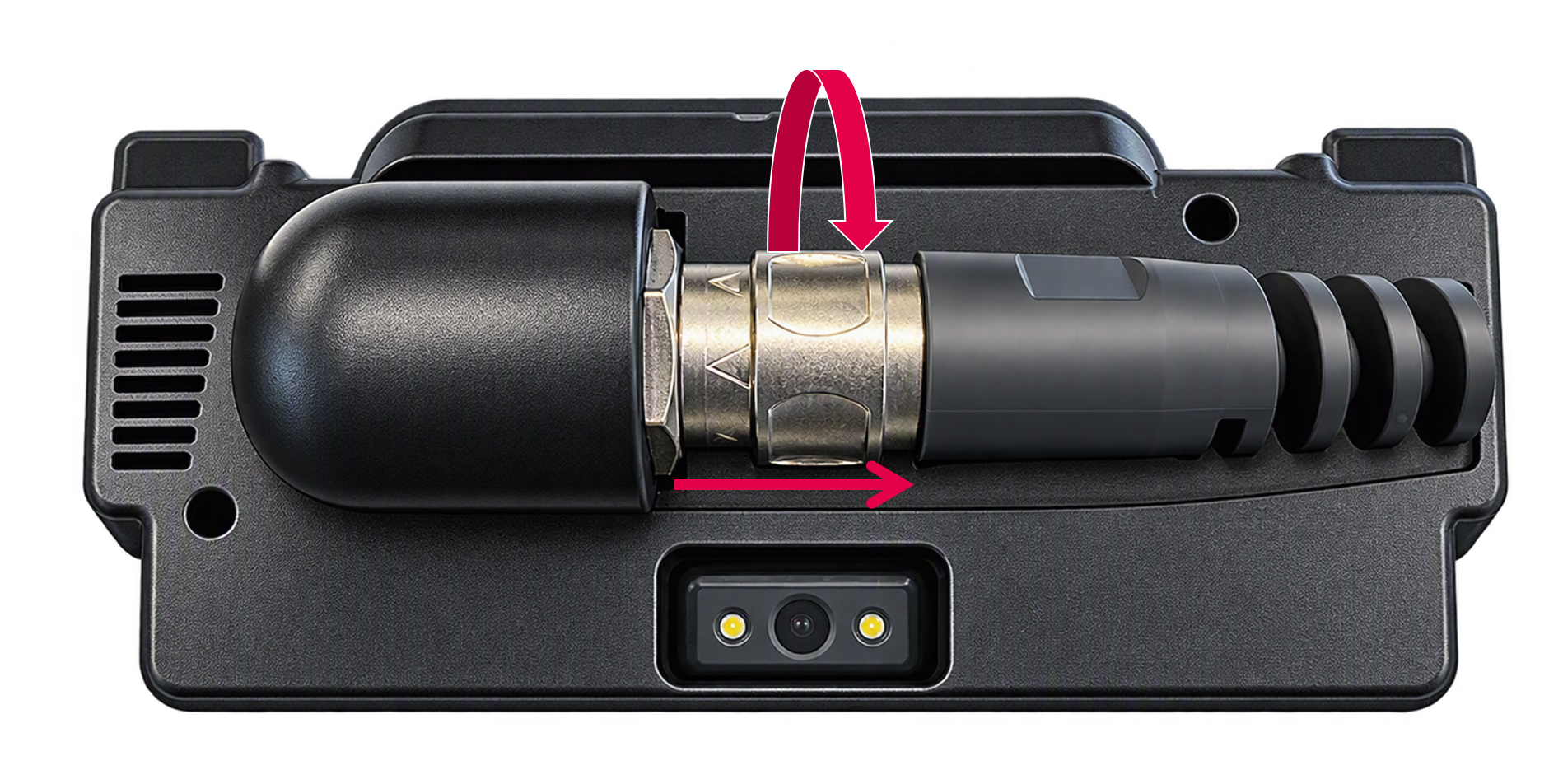
To remove the DLC cable, rotate the connector ¼ turn counter-clockwise and pull the cable away from the ES2504.
OBD extension cables
These cables are used to extend the OBD data connection and power supply between the vehicle diagnostic port and the main DLC of the ES2504.
The OBD extension cables are available in several lengths. Refer to Accessories and order information.
An illustration of the 2 m version of the OBD extension cable is shown below.