Mounting and placement
Mounting the BR_XETK-S3.0 into the ECU housing
|
NOTICE |
|---|
|
Damage to the electronics due to potential equalization The cables' shield may be connected to the housing, the ground or the ground for the product's power supply. If there are different ground potentials in the test setup, equalizing currents can flow between the products via the cables' shield. Take account of different electric potentials in your test setup and take appropriate measures to prevent equalizing currents. |
|
Note |
|---|
|
For all types of mounting the BR_XETK-S3.0 on the ECU housing, the gap pad has to be used! |
How to attach the BR_XETK-S3.0
There are different methods to attach the BR_XETK-S3.0 on the ECU housing:
-
Fixing the BR_XETK-S3.0 with mounting bracket.
-
Fixing the BR_XETK-S3.0 without mounting bracket.
|
Note |
|---|
|
ETAS recommends to attach the BR_XETK-S3.0 on the ECU housing with mounting bracket. |
Fixing the BR_XETK-S3.0 with mounting bracket
Mounting material
For mounting theBR_XETK-S3.0 on the ECU housing with mounting bracket following parts are needed:
-
Adhesive (recommended adhesive: LOCTITE SI 5145).
-
Mounting bracket for fixing on the ECU housing.
-
Gap pad for the thermal mounting to the ECU housing (including BR_XETKS3.0 delivery content or as spare part).
-
2 screws M2 x 4, Pan Head ISO 14583.
|
Number in figures |
Quantity |
Order Name |
Order Number |
|---|---|---|---|
|
1 |
1
|
BR_XETK-S3.0A Emulator Probe for the Infineon AURIX microprocessor family, delivery includes gap pad (F 00K 110 752) |
F 00K 110 751 |
|
or |
|
||
|
BR_XETK-S3.0C ECU interface for the Infineon AURIX TC4xx microcontroller family includes gap pad (F 00K 110 752) |
F 00K 113 470 |
||
|
2 |
1 |
Gap pad as spare part for BR_XETK-S3.0 |
F 00K 110 752 |
|
3 |
1 |
Mounting bracket for BR_XETK-S3.0 |
F 00K 110 753 |
|
4 |
2 |
Screw M2 x 4, Pan Head ISO 14583 |
- |
Mounting steps
To mount the BR_XETK-S3.0 into the ECU housing several mounting steps are required:
|
Note |
|---|
|
Observe the instructions for use provided by the adhesive manufacturer. Treat the bonding area before and hold the drying times. |
-
Apply the recommended adhesive on the mounting bracket.
-
Fit the mounting bracket at the intended location of the ECU housing.

-
The adhesive surfaces of the gap pad are protected with foils. Both foils must be removed before using the gap pad.
-
Fit the gap pad on the mounting bracket.
Bring the cutout of the gap pad into line with the ETK connectors.
The gap pad is self-adhesive.

-
Screw the BR_XETK-S3.0 with the ECU housing..
Fixing the BR_XETK-S3.0 without mounting bracket
This chapter describes an example to mount theBR_XETK-S3.0 without the mounting bracket. Mounting material excluding the gap pad has to be provided by customer for the special use case.
Mounting material
For mounting the BR_XETK-S3.0 on the ECU housing without mounting bracket following parts are needed:
-
Gap pad for the thermal mounting to the ECU housing (including BR_XETK-S3.0 delivery content or as spare part).
-
2 spacers (height = 2.30 mm, external diameter = 5.0 mm, M2 female thread).
-
2 screws M2 x 10, countersunk head.
-
2 nuts M2.
|
Number in figures |
Quantity |
Order Name |
Order Number |
|---|---|---|---|
|
1 |
1
|
BR_XETK-S3.0A Emulator Probe for the Infineon AURIX microprocessor family, delivery includes gap pad (F 00K 110 752) |
F 00K 110 751 |
|
or |
|
||
|
BR_XETK-S3.0C ECU interface for the Infineon AURIX TC4xx microcontroller family includes gap pad (F 00K 110 752) |
F 00K 113 470 |
||
|
2 |
1 |
Gap pad as spare part for BR_XETK-S3.0 |
F 00K 110 752 |
Preparing the ECU housing
-
Drill two holes through the ECU housing, see Mounting steps.
-
Lower the holes on the outer side of the ECU housing.
-
Insert the screws through the holes in the housing.
-
Screw the screws from the inside of the housing with the spacers.
-
Seal the housing with the holes.
Attaching the BR_XETK-S3.0 on the ECU housing
-
Place the gap pad correctly between the spacers.
-
Set the BR_XETK-S3.0 on the screws.
-
Attach the BR_XETK-S3.0 with nuts M2.
Connection to the ECU
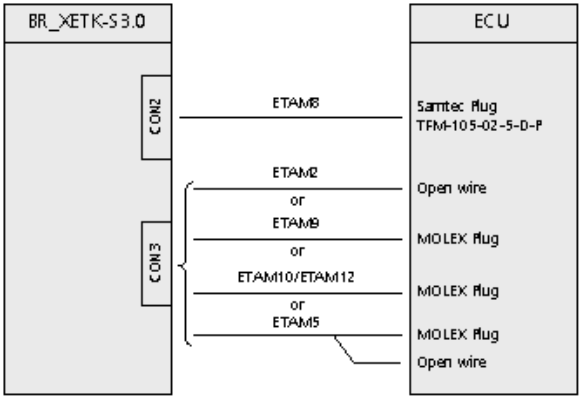
For connecting the BR_XETK-S3.0 to the ECU two XETK adapter cables are recommended:
-
at CON2 adapter ETAM8A or ETAM8B
-
at CON3 adapter ETAM2 or ETAM5 or ETAM9 or ETAM10/ETAM12
The adapter cables are to be ordered separately, see
The suitable connectors FCI-20 (CON2) and MOLEX-6 (CON3) should have been populated onto the ECU PCB for adapters ETAM8 and ETAM2/ ETAM5/ ETAM9/ETAM10/ETAM12