Hardware specifications BR_XETK-S3.0
Ambient conditions
|
Item |
Characteristics |
|
Operating temperature range |
- 40 °C to +110 °C - 40 °F to +230 °F |
|
Storage temperature range(without packaging) |
0 °C to +50 °C +32°F to +122 °F |
|
Max. relative humidity |
95% |
|
Max. altitude |
max. 5000 m/ 16400 ft |
|
Degree of contamination |
2 |
|
Protection rating (IEC 60529) |
Determined by installation in ECU |
|
Overvoltage category (mains supply) |
II |
|
Note |
|---|
|
Maximum Voltage to Earth or to any accessible parts (e.g. ECU Housing, Vehicle Chassis): 60V DC / 30V AC. |
Inside the ECU housing the maximum. temperature is specified with 110°C (230 °F), still air. Outside of the ECU housing the maximum ambient temperature is assumed to be 105°C(221 °F) at 1m/s airflow.
|
Note |
|---|
|
It is recommended to mount the BR_XETK-S3.0 via gap pad and mounting bracket directly to the ECU housing. |
Maximum thermal Resistance (Rth) BR_XETK-S3.0 glued mounting bracket surface to ambient air [ K/W ].
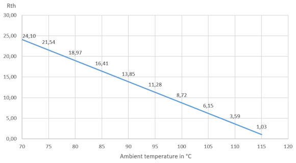
Rth = ( 125 - 8 - | T amb | ) / 1.95 K/W
Tjmax = 125°C (257°F)
Electrical data
|
Parameter |
Symbol |
Condition |
Min |
Typ |
Max |
Unit |
|
Permanent power supply |
UBatt |
Vehicle usage 1) |
6 |
12 |
36 |
V |
|
[all values ±0%] |
||||||
|
Cranking voltage |
UBatt |
< 3 seconds |
3 |
|
|
V |
|
Standby current |
ISTBY |
UBatt = 12 V; ECU off; |
30 |
40 |
50 |
mA |
|
Operating current |
IBatt |
UBatt = 12 V; |
90 |
135 |
250 |
mA |
|
Power dissipation |
PBatt |
UBatt = 12 V; |
|
1.62 |
|
W |
|
Power dissipation |
PBatt |
UBatt = 12 V; |
2.7 |
W |
||
|
Fuse in the ETK UBatt supply line. Only required if the power supply or ECU is not protected accordingly. |
MINI, 2 A 58 V DC (Littelfuse 0997002.WXN) |
|||||
|
Overvoltage category |
|
II | ||||
|
1) The BR_XETK-S3.0 implements reverse voltage protection in the same range and may be used only with central load dump protection. 24 V vehicles require UBatt disturbing pulse reduction to 12 V vehicle system. 12 V vehicles don’t require special disturbing pulse reductions. |
||||||
|
Note |
|---|
|
The BR_XETK-S3.0 will accept permanent power supply voltage dips (for additional details of 3 V low voltage operation, see ISO standard 16750). |
|
Note |
|---|
|
Maximum Voltage to Earth or to any accessible parts (e.g. ECU Housing, Vehicle Chassis): 60V DC / 30V AC. |
Maximum inrush current
It is highly recommended that the BR_XETK-S3.0 be connected to a permanent power supply. When this is not possible, or the BR_XETK-S3.0 must be powered off and back on in short intervals, time is required to reactivate the inrush limiting circuit of the BR_XETK-S3.0.
If the time between powering the ETK off and on is less than 40 seconds a high current peak can occur. If the above-mentioned fuse is used, this inrush current will not trigger the fuse. If other protection mechanisms are in place, the inrush current must be considered in the ECU design.
|
Time Between Powering Off and On |
Inrush Current Pulse ( UBatt = 12 V) |
|
> 40 s |
800 mA / 5 ms |
|
< 40 s |
18 A / 60 µs |
Microcontroller interface
BR_XETK-S3.0A
|
Parameter |
Symbol |
Condition |
Min |
Typ |
Max |
Unit |
|
ECU Standby RAM Output Voltage |
VDDSTBY |
max 500 mA load |
1.23 |
1.3 |
1.34 |
V |
|
VDDPSTBY |
VDDPSTBY |
max 80 mA load |
3.14 |
3.3 |
3.46 |
V |
|
Cal_Wakeup |
CAL_WAKEUP |
UBatt = 6 - 36 V; |
UBatt-1V |
|
UBatt |
V |
|
ECU Power Supply Supervision Voltage (3.3 V selected) |
VDDP
|
ECU on |
2.70 |
2.80 |
2.89 |
V |
|
ECU off |
2.44 |
2.54 |
2.66 |
V |
||
|
abs. max. |
|
|
5.50 |
|
||
|
IDDP |
VDDP 3.3 V |
|
|
200 |
mA |
|
|
ECU Standby RAM Supervision Voltage |
VDDSTBY /VDDSTBY-BY_SENSE IDDSTBY |
VDDSTBY |
1.02 |
1.12 |
1.22 |
V |
|
VDDSTBY ¯ |
1 |
1.1 |
1.2 |
V |
||
|
VDDSTBY 1.25 V |
|
|
73 |
mA |
BR_XETK-S3.0C
|
Parameter |
Symbol |
Condition |
Min |
Typ |
Max |
Unit |
|
ECU Standby RAM Output Voltage |
VDDSTBY |
max 500 mA load |
0.9 |
0.95 |
1 |
V |
|
VDDPSTBY |
VDDPSTBY |
max 80 mA load |
3.14 |
3.3 |
3.46 |
V |
|
Cal_Wakeup |
CAL_WAKEUP |
UBatt = 6 - 36 V; |
UBatt-1V |
|
UBatt |
V |
|
ECU Power Supply Supervision Voltage (3.3 V selected) |
VDDP
|
ECU on |
2.70 |
2.80 |
2.89 |
V |
|
ECU off |
2.44 |
2.54 |
2.66 |
V |
||
|
abs. max. |
|
|
5.50 |
|
||
|
IDDP |
VDDP 3.3 V |
|
|
200 |
mA |
|
|
ECU Standby RAM Supervision Voltage |
VDDSTBY /VDDSTBY-BY_SENSE IDDSTBY |
VDDSTBY |
0.84 |
0.87 |
0.90 |
V |
|
VDDSTBY ¯ |
0.82 |
0.85 |
0.88 |
V |
||
|
VDDSTBY 0.95 V |
|
|
73 |
mA |
Power-on delay of ECU reset
|
Parameter |
Symbol |
Condition |
Min |
Typ |
Max |
Unit |
|
Reset delay 1 Delay of ECU reset through ETK without transferring the FPGA (UBatt present, VDDP will be switched on) |
tReset1 |
UBatt = 12 V ECU_VDDP goes high |
3 |
5 |
20 |
ms |
|
Reset delay 1 max. delay of ECU reset through ETK (UBatt and VDDP will be switched on) |
tReset2 |
UBatt goes high |
100 |
|
240 |
ms |
ECU interface connector
|
Signal |
Pin Type |
VOL |
VOH |
VOH |
VIL |
VIH |
VIH |
Leakage current |
Additional load by ETK 1) (typ) [pF] |
|
DAP0 |
XO1) |
0.7 |
2.3 |
3.3 |
- |
- |
- |
+631 |
10 |
|
DAP1 |
IXO1) |
0.7 |
2.3 |
3.3 |
0.8 |
2 |
5.5 |
+5000 / +3340 |
10 |
|
DAP2 |
IXO1) |
0.7 |
2.3 |
3.3 |
0.8 |
2 |
5.5 |
+5000 / +3340 |
10 |
|
RESERVED |
XO1) |
0.7 |
2.3 |
3.3 |
- |
- |
- |
+20 / -20 |
10 |
|
/TRST |
XO2) |
0.7 |
2.3 |
3.3 |
- |
- |
- |
+20 / -20 |
10 |
|
/ESR0 |
IXOD3) |
0.7 |
- |
- |
0.8 |
2 |
5.5 |
+25 / -20 |
22 |
|
/PORST |
IXOD3) |
0.7 |
- |
- |
0.8 |
2 |
5.5 |
+25 / -20 |
22 |
|
WDGDIS |
XO2)) |
0.7 |
2.3 |
3.3 |
- |
- |
- |
+20 / -20 |
10 |
|
DAPE0 |
XO2)) |
0.7 |
2.3 |
3.3 |
- |
- |
- |
+631 |
10 |
|
DAPE1 |
IXO1) |
0.7 |
2.3 |
3.3 |
0.8 |
2 |
5.5 |
+5000 / +3340 |
10 |
|
DAPE2 |
IXO1) |
0.7 |
2.3 |
3.3 |
0.8 |
2 |
5.5 |
+5000 / +3340 |
10 |
|
GATE_PROST |
I |
0.7 |
2.3 |
3.3 |
0.8 |
3 |
3.8 |
+165 |
15 |
|
TDI |
XO2)) |
0.7 |
2.3 |
3.3 |
- |
- |
- |
+20 / -20 |
10 |
|
Pin Type: |
|||||||||
|
1) Adapter cable and Samtec connector not considered; PCB 1 pF/cm |
|||||||||
DAP timing characteristics

The BR_XETK-S3.0 supports two DAP modes:
-
2-pin DAP mode: one data pin (direction via protocol), one clock pin
-
3-pin DAP mode: two data pins (bidirectional, direction via protocol), one clock pin
The 2-pin DAP mode is the BR_XETK-S3.0 DAP interface default mode.
|
Note |
|---|
|
DAP timing parameters in this chapter refer to the DAP interface (CON2) of the BR_XETK-S3.0. The DAP wiring to the ECU (ETAM8) must be taken account additionally. All timings are measured at a reference level of 1.5 V. |
2-pin DAP mode
|
Parameter |
Symbol |
Value [ns] |
Comment |
|
DAP0 Clock Period |
tCLK |
10 |
100MHz DAP Clock |
|
20 |
50 MHz DAP Clock Frequency |
||
|
DAP1 Set-Up Time |
tSU |
4 |
|
|
DAP1 Hold Time |
tH |
2 |
|
|
DAP1 Clock-to-Out Time (Target --> ETK) |
tCO |
~ |
Undetermined, ETK automatically determines optimum sampling point |
3-pin DAP mode
|
Parameter |
Symbol |
Value [ns] |
Comment |
|
DAP0 Clock Period tCLK
|
6.25 |
160MHz DAP Clock Frequency |
|
|
10 |
100 MHz DAP Clock Frequency |
||
|
20 |
50 MHz DAP Clock Frequency |
||
|
DAP1 Set-Up Time |
tSU |
4 |
|
|
DAP1 Hold Time |
tH |
2 |
|
|
DAP1 Clock-to-Out Time (Target --> ETK) |
tCO |
~ |
Undetermined, ETK automatically determines optimum sampling point |
Mechanical data
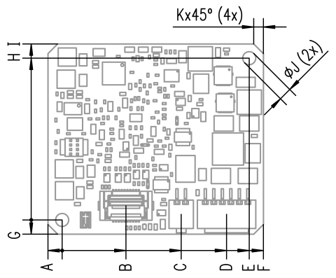
The reference measure for all drawings is millimeters.
Top view
|
Item |
Dimension [mm] |
Tolerance [mm] |
Dimension [in] |
Tolerance [in] |
|---|---|---|---|---|
|
A |
2.50 |
+/- 0.1 |
0.098 | +/- 0.004 |
|
B |
11.25 |
+/- 0.1 |
0.443 | +/- 0.004 |
|
C |
21.00 |
+/- 0.2 |
0.827 | +/-0.008 |
|
D |
29.00 |
+/- 0.2 |
1.142 |
+/-0.008 |
|
E |
33.00 |
+/- 0.2 |
1.299 |
+/-0.008 |
|
F |
35.50 |
+/- 0.2 |
1.398 |
+/-0.008 |
|
G |
2.50 |
+/- 0.1 |
0.098 |
+/- 0.004 |
|
H |
28.50 |
+/- 0.2 |
1.122 |
+/-0.008 |
|
I |
31.00 |
+/- 0.2 |
1.220 |
+/-0.008 |
|
J |
2.30 |
+ 0.1 /- 0.0 |
0.091 |
+ 0.007 / - 0.000 |
|
K |
1.00 |
+/- 0.1 |
0.039 |
+/- 0.004 |
Side view

|
Item |
Dimension [mm] |
Tolerance [mm] |
Dimension [in] |
Tolerance [in] |
|---|---|---|---|---|
|
A |
2.00 | + 0.0 /- 0.2 | 0.079 | + 0.000 / - 0.008 |
|
B |
1.60 | + 0.16 /- 0.16 | 0.063 | + 0.006 / - 0.006 |
|
C |
.510 | + 0.0 /- 0.2 | 0.201 | + 0.000 / - 0.008 |