Interfaces
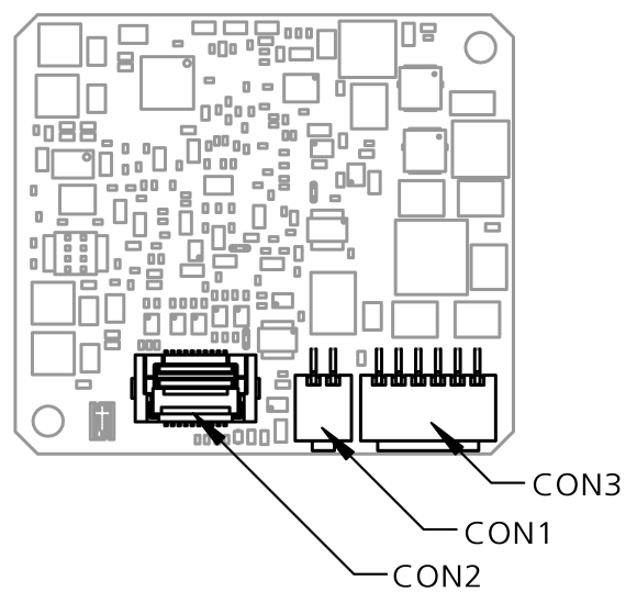
Automotive ethernet interface CON1
The Automotive Ethernet interface (100BASE-T1) of the BR_XETK-S3.0 cannot be connected to a PC directly, but a media converter has to be inserted in between.
Its purpose is to transform the physical layers of Automotive Ethernet (1 differential pair / 2 wires) into Standard Ethernet (2 differential pairs/ 4 wires) and vice versa. The media converter has to be connected to CON1.
The combination of the BR_XETK-S3.0 and the Automotive Ethernet media converter CBEB100.1, ES160.1, ES162.1, and ES165.1 is integrated in the ETAS IP worldb with automatic IP management and supports the open automotive "Universal Measurement and Calibration" standard "XCP on Ethernet" (TCP/IP, UDP/IP).
The open "XCP on Ethernet" interface allows for connecting to the BR_XETK-S3.0 with third party application software.
|
Note |
|---|
|
The Automotive Ethernet interface is not compatible with the standard Ethernet interfaces of ETAS modules. An Automotive Ethernet Media Converter or an ES88x ECU Interface Module is needed to connect the BR_XETK-S3.0 to the PC. |
ECU interface CON2
The BR_XETK-S3.0 is connected via connector CON2 to the ECU with an adapter cable. The pin definition depends on the application and the microcontroller type. In general, the ECU interface consists of
-
1 ECU voltage line, which is not used for XETK power supply, but only for detection of the ECU status, therefore the power consumption on this line is negligible.
-
1 Reset line which allows the XETK to control and monitor the system reset of the ECU.
-
1 Reset line which allows the XETK to control and monitor the power-on reset of the ECU.
-
5 Debug lines for the communication between the BR_XETK-S3.0 and the microcontroller.
-
5 ground lines for proper shielding of the ECU interface lines.
Power supply interface CON3
The BR_XETK-S3.0 requires a permanent power supply. It is typically powered directly from the car battery. The input voltage may vary, see Technical specifications. In case of higher input voltages to the XETK, additional voltage protection is required. The BR_XETK-S3.0 will also accept voltage dips down to 3 V (for additional details of low voltage operation, see ISO standard 16750).
From the input battery voltage, switch-mode power supplies provide all necessary voltages on the BR_XETK-S3.0. The power supply of the ECU is not affected by the BR_XETK-S3.0. An automatic switch ensures that the power consumption of the BR_XETK-S3.0 is reduced to a minimum, when the BR_XETK-S3.0 enters its standby (sleep) mode.
The BR_XETK-S3.0 is supplied with power through the connector CON3.
DAP interface
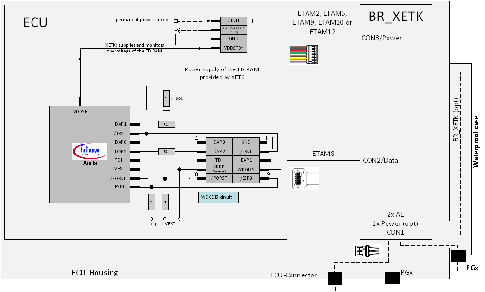
The BR_XETK-S3.0 operates the Device Access Port (DAP) interface in the 2-pin or in the 3-pin DAP mode.
Infineon recommends 22 Ohm resistors for DAP1 (R1) and DAP2 (R2) on the ECU board. However according the ETAS experience the DAP interface with 0 Ohm resistors is more robust.
-
All DAP traces should be of equal length; DAP0 is the reference for DAP1 and DAP2.
-
The DAP lines should be kept as short as possible.
-
Avoid stubs. If unavoidable, stubs should be kept as short as possible and reduce the DAP frequency if necessary.
-
Route the DAP Traces single-ended with approximately 50 Ohm impedance.
-
Minimize crosstalk between DAP traces in the layout, especially for DAP0.
|
Note |
|---|
|
Power Supply of the ED RAM: Use only with supported controllers. |