State Machines
A state machine is a special type of classes, an event-driven system where the focus is not on computations but on control flow. Therefore the main level of description of a state machine, the state diagram, does not describe how data, but how control is passed. To model control flow, a state machine consists of a finite number of states, and transitions between these. Besides, at least one trigger must be included to control the state machine. At each trigger call, one step of the state machine is executed.
For more information on the theory of finite state machines, see
- Harel, David: "Statecharts: A Visual Formalism for Complex Systems", Science of Computer Programming 8, 1987, pp. 231-274
- Hatley, Derek J. & Imtiaz A. Pirbhai, Strategies for Real-Time System Specification, Dorset House Publishing Co., Inc., NY, 1988.
A state machine consists of a state diagram and additional normal block diagrams or ESDL diagrams. The following diagram shows the components of a state machine.
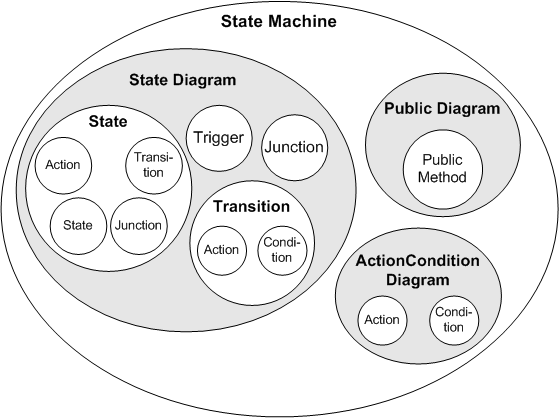
The state diagram is a special block diagram, where the states are represented as rectangles with rounded corners, and the transitions by directed arcs. Every state can be a hierarchy state i.e. a state containing another state diagram. One of the states always has to be marked as the start state, this is the state the machine is in at the beginning. The actions and conditions of a state machine are specified in additional block diagrams or in ESDL. Additional public methods can be specified in separate diagrams.
The transitions are targeted curves between the states. Each arc represents one transition in a direction marked by an arrowhead at one end. Each end of a transition is connected to a state or junction. The state where the transition starts is the source state, the one where it ends is the destination state. Two arcs are necessary to model a bidirectional transition.
Specifying a state machine consists of determining the states a system can be in, defining the conditions that have to be fulfilled for changing from one state to another, and determining the actions that are to be performed during these transitions. Specifying state machines is similar to specifying block diagrams, and you can also use block diagrams as parts of a state machine. Many parts of the description of block diagram editor functionality are the same for the state machine editor. These parts are not described separately here, so before reading this chapter, you should be familiar with specifying block diagrams in the block diagram editor.
Specifying a state machine consists of the following steps, which are described in this part of the ASCET online help:
- Drawing a state diagram (i.e. arranging the states and transitions).
- Specifying the conditions and actions.
- Assigning the conditions and actions to the states and transitions in the state diagram.
- Specifying public methods in a separate diagram.
See also
Specifying Conditions and Actions