Expressions
Expressions are formed in software components by connecting elements or other expressions with operators. Like in ESDL, expressions are built up recursively, as follows:
- An element is an expression.
- The result of an operation is an expression (the operands itself are expressions).
- The return value of a method call is an expression. If arguments are supplied to the method, these arguments also belong to the expression.
The range of an expression is therefore limited by the base expressions in that expression, which are either elements or return values of methods without arguments.
In the block diagram editor for software components, expressions are built graphically by connecting the return pins of elements or operators with the argument pins of methods or other operators.
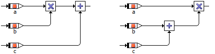
There are no precedence rules for operators in the block diagram editor for software components, since the expressions are “bracketed” by the way the lines and operators are connected. The following example shows the difference between the expressions (a*b)+c and a*(b+c) in the graphical representation.
The evaluation order of the arguments of operators is sometimes very important. In the graphical representation this sequence is always from top to bottom, except for the four basic arithmetic operators with at most three inputs. The order of evaluation is illustrated in the following diagram:

In software components specified as block diagrams, the number of arguments to the operators is often limited to a maximum of 10 or 20 inputs. The evaluation order of method arguments depends on the order in which they are defined. Since the layout of an element can be changed, the order in the layout does not necessarily coincide with that in the definition.