Graphical Description of Elements
Every element and operator used in a component is graphically represented by a diagram item in the form of a rectangle. The interaction between these elements is represented by lines connecting the corresponding diagram items.
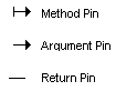
The interface of an element is represented graphically by pins (first figure). Each argument of a method is represented by an argument pin (with a little arrow head pointing towards the block) at the block frame. The return values are represented by a return pin. The call to a method is associated with its return pin. Methods without arguments or return values are represented by a method pin.
The name of the element is placed underneath the rectangle. An icon can be used to illustrate the functionality of an element. The position of the pins can be changed by the user.
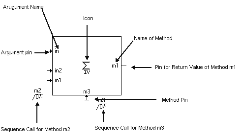
The example in the second figure shows a complex element with three methods. Method m1 has one argument and a return value. Method m2 has no return value and is represented by its arguments, method m3 has neither arguments nor a return value and is represented by a method pin.